
[vc_row][vc_column][vc_column_text]
Detailed Information About Diaphragm Valve From UPVC Pipe Manufacturer
Diaphragm valves restrict, regulate, or isolate fluid flow using a flexible diaphragm. The flow control element is the diaphragm, which bends up or down to raise or reduce the fluid flow rate. The diaphragm is forced against the solid dam inside the valve body to provide the valve’s sealing action. Linear motion valves, such as diaphragm valves, need linear motion of the flow control element. Check Petron Thermoplast, the UPVC Pipe Manufacturer product.
Slurries, colloids, sludges, and brackish water are all handled successfully by diaphragm valves, which can handle liquids, gaseous fluids, and semi-solid media. These valves are appropriate for dealing with liquids that include solid particles. They have a significantly simpler structure than other valves. The build-up of sediments and biofilms in diaphragm valves is less likely due to the low contact made by their interior components. As a result, diaphragm valves are commonly used in the food and pharmaceutical industries, as well as water treatment, sewage pipelines, and treatment facilities, electronics manufacturing, and pulp and paper manufacture.[/vc_column_text][/vc_column][/vc_row][vc_row][vc_column][vc_column_text]
Technical Specification
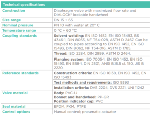 [/vc_column_text][vc_column_text]
Components of Diaphragm Valves
Bonnet
The valve body is fastened to the bonnet, which acts as the top cover. It safeguards the diaphragm valve’s compressor, stem, diaphragm, and other non-wetted components.
Valve Body
The valve body is the component that is directly attached to the pipeline through which the fluid flows. Depending on the kind of diaphragm valve, the flow area inside the valve body varies. The valve body and bonnet are made of materials that are robust, stiff, and corrosive resistant.
Diaphragm
The diaphragm is a highly elastic polymeric disc that glides down to meet the valve body’s bottom to restrict or impede fluid flow. If the fluid flow rate is raised or the valve is fully opened, the diaphragm lifts. Underneath the diaphragm, fluid flows. However, due to the material and construction of the diaphragm, this component restricts the valve’s operational temperature and pressure. It must also be changed on a regular basis since its mechanical characteristics deteriorate over time.
The non-wetted components (compressor, stem, and actuator) are isolated from the flowing medium by the diaphragm. As a result, particles and viscous fluids are less likely to obstruct the diaphragm valve’s operation mechanism. Non-wetted components are likewise protected against corrosion. The lubricant needed to operate the valve, on the other hand, will not contaminate the fluid in the pipeline.
Compressor
Between the valve stem and the diaphragm is a disc called the compressor. During linear movement, it supports the diaphragm valve and distributes the stresses from the stem. The compressor has been tweaked to improve flow throttling and control.
Stem
The stem is a vertical shaft attached to the compressor that moves both the compressor and the diaphragm in a linear motion, thereby activating the diaphragm valve. It is responsible for transmitting the actuator’s motion. The stems of diaphragm valves can be piston or threaded. Piston-type valves are controlled by a piston assembly located within the bonnet, with the valve stem serving as the piston rod. This kind necessitates the application of a linear force generated by fluid pressure. A stem nut is included with threaded stem valves. Torque is required to move the stem linearly, as well as lubrication for smooth action.[/vc_column_text][/vc_column][/vc_row][vc_row][vc_column][vc_column_text]Diaphragm valves’ threaded stems might have a rising or non-rising mechanism:
- Rising Stem
Rising stems, also known as signaling stems, stretch all the way to the handwheel. The stem rises or falls as the handwheel are cranked, opening or closing the valve. As a result, looking at the quantity of stem visible makes it easy to estimate the extent to which the valve is opened. Rising stems, on the other hand, take up more space than non-rising stems.
- Non-Rising Stem
Non-rising stems, also known as non-indicating stems, are turned to open or close the valve, but not up or down. In tight areas, such as subterranean plumbing systems, non-rising stem valves are employed.[/vc_column_text][/vc_column][/vc_row][vc_row][vc_column][vc_column_text]
Actuator
The valve actuator moves the stem, compressor, and diaphragm all at the same time. It gives the diaphragm valve the torque or linear force it needs to adjust the fluid flow rate quickly. The valve stem’s structure has an impact on the actuator. The types of actuators used in diaphragm valves are listed below.
- An operator adds torque to a manual actuator using a handwheel or a crank. This torque is required to spin the threaded stem and, as a result, move linearly in order to change the fluid flow rate. These actuators, on the other hand, have slower control speeds and need greater effort to operate. Gearheads can be used to boost torque and improve the opening and closing speeds. On manual actuators, features like lockability, stroke adjustment, position indicator, and electrical feedback switches can be implemented.
- Electric actuators use a motor to change the rate of fluid flow. To lower the speed and enhance the torque, the electric motor is linked to the gear train. These valves are reversible, meaning they can open a diaphragm valve from a closed state and close it again.
- Pneumatic actuators use air pressure to move the piston within the valve bonnet, which is linked to the compressor by its piston rod. On both sides of the piston, air pressure is provided to the chamber. When air is injected into the piston’s upper chamber, the piston rod moves down, lowering the fluid flow rate or closing the valve. If air is not provided in the lower chamber, the piston rod will rise higher, increasing the fluid flow rate. To prevent air leakage across both chambers, O-rings are placed in the piston rod and piston. Pneumatic actuators are used in throttle diaphragm valves and on/off applications to offer fast-acting control.
- Hydraulic actuators use hydraulic fluids like oil or water to exert a considerable force on a diaphragm valve to open or close it. Typically, these actuators are utilized in lower-speed applications.
- A change in temperature in the flowing medium activates thermal actuators. The fluid flow rate is controlled by this activation.
[/vc_column_text][/vc_column][/vc_row][vc_row][vc_column][vc_column_text]
Position Indicators
Position indications are visual cues that help distinguish whether the diaphragm valve is open or closed. It might be a light, a switch, or even a stem. Some valves include piston indications that show which way the flow is going.
Connection
Diaphragm valves can be linked in a number of different ways. Diaphragm valves are connected to the pipeline via threads, compression fittings, bolt flanges, clamp flanges, tube fittings, butt welds, socket welds, and metal face seals.[/vc_column_text][/vc_column][/vc_row][vc_row][vc_column][vc_column_text]
About Petron UPVC Pipe Manufacturer’s Diaphragm Valve
This Diaphragm valve has two or more ports and is an on-off throttle valve. Diaphragm valves are divided into two categories:
- The first type – Seals over the weir. It is best used to control small flows.
- The second type – Seals over the seat. It is used where the flow direction changes within the system.
When choosing a diaphragm valve, it’s critical to understand how to choose the right size. The volume of media passing through the system determines the size. The composition of the material used to manufacture the diaphragm determines its quality. It can be built out of rubber-lined glass, plastic-lined plastic, and various solid metals and solid polymers that are both expensive and inexpensive.

Main characteristics
- New body design à Higher flow rate factor
- Improved linearity in case of flow regulation
- Ergonomic handwheel and bonnet in PP-GR with PVC cap (excellent chemical resistance)
- Patented system to adjust and lock the flow in over 300 positions
- DK Limited version to set the flow
- Possibility to tag
- Monolithic flanged body
- Available in UPVC, CPVC, PPH, PVDF
[/vc_column_text][/vc_column][/vc_row]


Your point of view caught my eye and was very interesting. Thanks. I have a question for you.