


PRESSURE VARIATION ACCORDING TO TEMPERATURE
For water and non-hazardous fluids with regard to which the material is classified as CHEMICALLY RESIS-TANT. In other cases, a reduction of the nominal pressure PN is required(25 years with safety factor).

PRESSURE DROP GRAPH

KV 100 FLOW COEFFICIENT
The Kv 100 flow coefficient is the Q flow rate of litres per minute of water at a temperature of 20°C that will generate Δp= 1 bar pressure drop at a certain valve position. The Kv100 values shown in the table are calculated with the valve completely open.
| DN | 15 | 20 | 25 | 32 | 40 | 50 | 65 |
|---|---|---|---|---|---|---|---|
| Kv100 l/min | 112 | 261 | 445 | 550 | 1087 | 1648 | 1600 |
RELATIVE FLOW COEFFICIENT GRAPH
The relative flow coefficient is the flow rate through the valve as a function of the degree of valve opening. Horizontal axis: Percentage opening
of the disk Vertical axis: Relative flow coeffi-cient

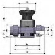
DKUIV
Hand operated Butterfly valve
| d | DN | PN | B | B1 | E | H | H1 | La | R1 | Z | g | EPDMcode | FKMcode | PTFEcode |
|---|---|---|---|---|---|---|---|---|---|---|---|---|---|---|
| 20 | 15 | 10 | 102 | 25 | 41 | 129 | 80 | 90 | 1″ | 100 | 500 | DKUIV020E | DKUIV020F | DKUIV020P |
| 25 | 20 | 10 | 105 | 30 | 50 | 154 | 80 | 108 | 1″1/4 | 116 | 562 | DKUIV025E | DKUIV025F | DKUIV025P |
| 32 | 25 | 10 | 114 | 33 | 58 | 168 | 80 | 116 | 1″1/2 | 124 | 790 | DKUIV032E | DKUIV032F | DKUIV032P |
| 40 | 32 | 10 | 119 | 30 | 72 | 192 | 80 | 134 | 2″ | 140 | 916 | DKUIV040E | DKUIV040F | DKUIV040P |
| 50 | 40 | 10 | 149 | 35 | 79 | 222 | 120 | 154 | 2″1/4 | 160 | 1768 | DKUIV050E | DKUIV050F | DKUIV050P |
| 63 | 50 | 10 | 172 | 46 | 98 | 266 | 120 | 184 | 2″3/4 | 190 | 2668 | DKUIV063E | DKUIV063F | DKUIV063P |
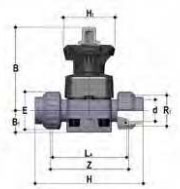
DKOV
DIALOCK® diaphragm valve with flanged monolithic body, drilled PN10/16. Face to face
according to EN 558-1
| d | DN | PN | B | B1 | F | f | H | H1 | Sp | U | g | EPDMcode | FKMcode | PTFEcode |
|---|---|---|---|---|---|---|---|---|---|---|---|---|---|---|
| 20 | 15 | 10 | 102 | 25 | 65 | 14 | 130 | 80 | 4 | 13.5 | 925 | DKOV020E | DKOV020F | DKOV020P |
| 25 | 20 | 10 | 105 | 30 | 75 | 14 | 150 | 80 | 4 | 13.5 | 990 | DKOV025E | DKOV025F | DKOV025P |
| 32 | 25 | 10 | 114 | 33 | 85 | 14 | 160 | 80 | 4 | 13.5 | 1054 | DKOV032E | DKOV032F | DKOV032P |
| 40 | 32 | 10 | 119 | 30 | 100 | 18 | 180 | 80 | 4 | 14 | 1272 | DKOV040E | DKOV040F | DKOV040P |
| 50 | 40 | 10 | 149 | 35 | 110 | 18 | 200 | 120 | 4 | 16 | 2164 | DKOV050E | DKOV050F | DKOV050P |
| 63 | 50 | 10 | 172 | 46 | 125 | 18 | 230 | 120 | 4 | 16 | 3009 | DKOV063E | DKOV063F | DKOV063P |
| 75 | 65 | 10 | 172 | 46 | 145 | 18 | 290 | 120 | 4 | 21 | 3610 | DKOV075E | DKOV075F | DKOV075P |
EXPLODED VIEW
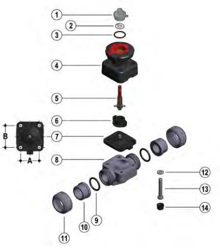
| DN | 15 | 20 | 25 | 32 | 40 | 50 | 65 |
|---|---|---|---|---|---|---|---|
| A | 40 | 40 | 46 | 46 | 65 | 78 | 78 |
| B | 44 | 44 | 54 | 54 | 70 | 82 | 82 |
- 1 Transparent protection cap(PVC – 1)*
- 2 Customisation plate (PVC-U – 1)
- 3 O-Ring (EPDM – 1)
- 4 Operating mechanism (PP-GR /PVDF – 1)
- 5 Threaded stem – Indicator(STAINLESS steel – 1)
- 6 Compressor (PA-GR IXEF® – 1)
- 7 Diaphragm seal (EPDM, FKM,PTFE – 1)*
- 8 Valve body (PVC-U – 1)*
- 9 Socket seal O-Ring (EPDM-FKM- 2)*
- 10 End connector (PVC-U – 2)*
- 11 Union nut (PVC-U – 2)*
- 12 Washer (STAINLESS steel – 4)
- 13 Bolt (STAINLESS steel – 4)
- 14 Protection plug (PE – 4)
- 15 Distance plate (PP-GR – 1)**
- 16 Screw (STAINLESS steel – 2)**
* Spare parts
** Accessories
The material of the component and the quantity supplied are indicated in brackets