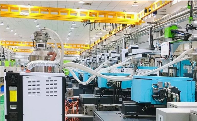
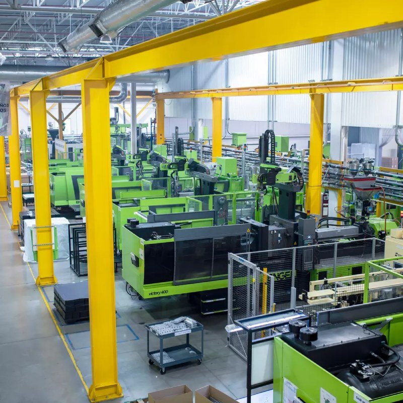
Our manufacturing units strengthen our business. We have the latest technological systems.
350+
PRODUCT RANGES
There is a wide range of product categories available to fulfill every need of the Customers.
1600+
SATISFIED CUSTOMERS
Every customer is a premium customer for us. We provide them the best quality of services.
20+
MECHANICAL ENGINEERING
Give us a try, and you won’t regret it – we specialize in product maintenance
ABOUT US
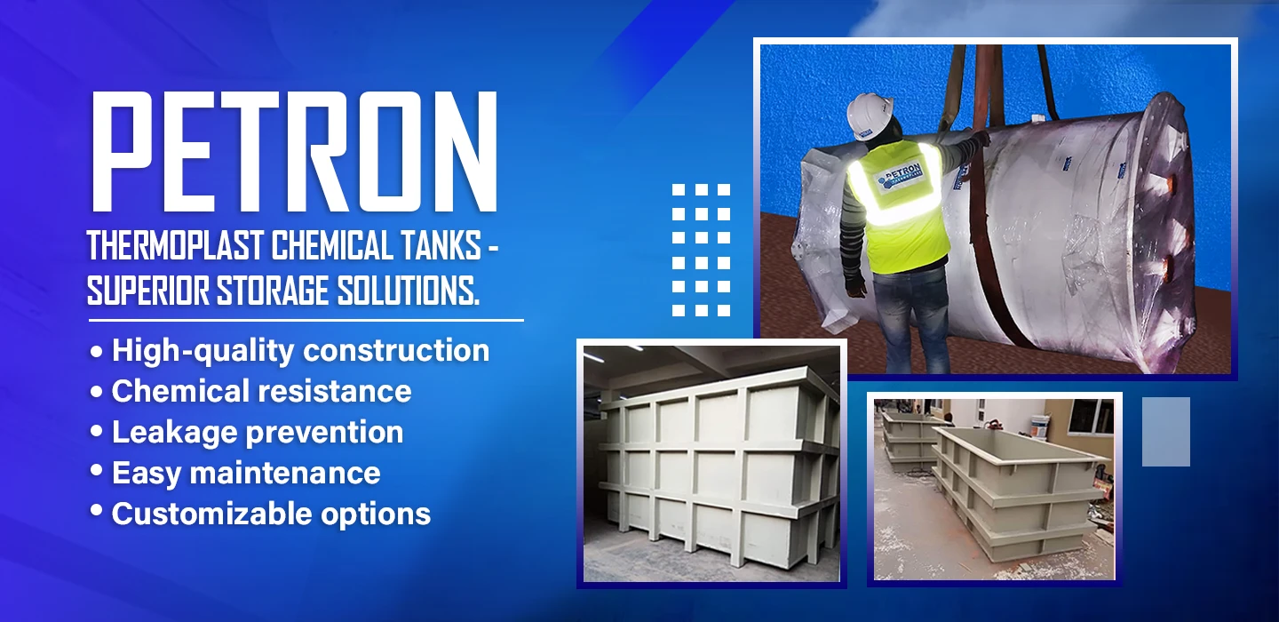
Industry Solution For Engineering Plastic Components
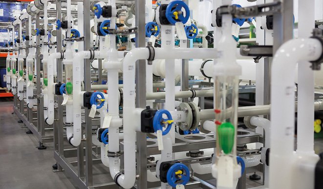
The PETRON THERMOPLAST is a leading pipe manufacturers & consultant in India for Thermoplastic Industrial engineering products and taking Industrial turnkey to supply & installation, fabrication of All type of Industrial Thermoplastic piping systems like CPVC, UPVC, PVDF, PPH, HDPE, ABS etc.
For chemical, waste water treatment plants. Primarily Thermoplastic chemical fluid & waste water handling systems used in industrial and public infrastructure applications.
Our mission is to become the market leader by becoming one of the providers of the best quality products. On the other hand, we are committed to work closely with our valued customers to understand their long term needs.
We ensure that all projects are done with the utmost professionalism, using quality materials, while offering clients the support and accessibility they deserve.
The advantages of our company are in the quality of products
We offer a wide range of industry solutions for Engineering Plastic Components that are used for manufacturing Plastics & Custom Molding. The field of industry solutions for engineering plastics materials has traditionally focused on supplying high-quality plastic and products for engineering plastic manufacturing in India.
The industry solution for engineering plastic components is common due to their wide range of benefits. Engineering Plastics are often a convenient solution for plastic components such as tamper-proof packaging to ensure safe shipment, with proper design quality check and other key parts.
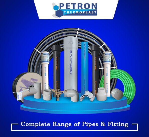
Petron Thermoplast is the leading Supplier, Wholesaler, Dealer, Trader, and Manufacturer for a wide range of Pipe Fittings. Our company products are of high-quality from thermoplastic manufacturers worldwide, providing with reliable services. We are strongly focused in providing Thermoplastic products which are used for UPVC, CPVC, PPH, ABS, PVDF, HDPE, PVC Pipes and Fittings. Our company products are procured by our customers from both domestic and international regions.
At Industify Company, we rely on honesty, discipline and hard work and believe our success can be attributed to upholding a simple set of core values that date back to the beginning of the company.
We went above and beyond to create a fantastic experience. Perfectly crafted to suite your industrial business with almost unlimited options to get almost unlimited options.
Industry Solution For Engineering Plastic Components
1. What are thermoplastic products?
Thermoplastic products are a type of plastic that can be repeatedly melted and reshaped without losing their original properties. They are commonly used in a wide range of applications, including packaging, automotive parts, and consumer goods.
2. What are the most common types of thermoplastic products?
The most common types of thermoplastic products include polyethene, polypropylene, polyvinyl chloride, polystyrene, and polycarbonate.
3. What are the advantages of using thermoplastic products?
Thermoplastic products are lightweight, durable, and easy to shape and mould. They also have excellent chemical resistance and can withstand high temperatures.
4. What are the disadvantages of using thermoplastic products?
Thermoplastic products may not be as strong as thermosetting plastics, and they may not be suitable for applications that require high levels of impact resistance. They are also not biodegradable.
5. How are thermoplastic products recycled?
Thermoplastic products can be recycled by shredding or grinding them into small pieces, then melting and moulding them into new products. However, not all types of thermoplastic products can be recycled, and the recycling process can also depend on the quality of the material.