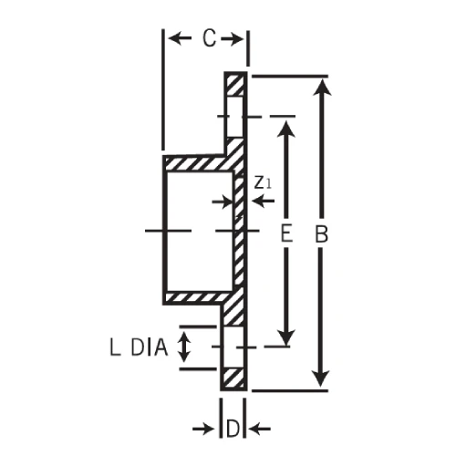
The ABS Full Face Flange is a critical component used to connect ABS piping systems securely and efficiently. Designed with a full face, this flange offers maximum sealing surface area, ensuring leak-proof joints when bolted to other flanged components like valves, pumps, or equipment. Manufactured from durable ABS (Acrylonitrile Butadiene Styrene), the full face flange is lightweight, corrosion-resistant, and ideal for low to medium pressure piping applications in plumbing, irrigation, and industrial fluid systems.
Full Face Design – Provides a large sealing surface for superior leak prevention Durable ABS Material – Ensures high impact strength and corrosion resistance Easy Installation – Bolt-hole pattern compatible with standard flanged equipment Lightweight Construction – Simplifies handling and reduces installation time Chemical & Corrosion Resistant – Suitable for non-aggressive fluids and environments UV Stabilized – Can be used indoors or outdoors without degradation Available in Multiple Sizes – Compatible with various ABS pipe diameters and flange standards Low Maintenance – Requires minimal upkeep over its service life
Technical Information
Parameter
Details
Product Name
ABS Full Face Flange
Material
Acrylonitrile Butadiene Styrene (ABS)
Connection Type
Flanged
Available Sizes
½”, ¾”, 1″, 1¼”, 1½”, 2″, 3″, 4″ and custom sizes
Operating Temperature
-20°C to +70°C
Working Pressure
Up to 10 bar
Color
Black or Grey
Standards
Complies with ASTM, ISO, and BS specifications
Applications
Plumbing, irrigation, drainage, HVAC, and industrial piping systems
If you are searching for customized product designs that meet your requirements, don’t worry. Petron Thermoplast also offers custom product manufacturing services to meet the unique needs of various industries. Work with our expert engineers to create custom designs suited for your application.