UPVC Reducer Coupler image 2 UPVC Coupler Images 1 UPVC Reducer Coupler image 3

UPVC Reducer Coupler

UPVC Reducer Coupler fittings are used to connect two UPVC pipes of different diameters while maintaining a clean, aligned flow path. Industries support projects that need reliable size transitions in chemical distribution, irrigation, drainage, and industrial utility lines. A properly selected UPVC reducer coupler helps minimize leakage risks, improves joint stability, and simplifies layout changes when a line moves from a main header to a smaller branch. With consistent dimensions and smooth internal bore, reducer couplers help maintain flow efficiency and reduce turbulence compared to improvised transitions. Contractors and maintenance teams also make repairs faster by allowing direct coupling of available pipe sizes without redesigning the entire run.

A UPVC reducer coupler works by providing two socket ends with different internal diameters inside one fitting body. The larger side accepts the main pipe, and the smaller side accepts the reduced pipe size. Installation typically uses solvent cement welding for uPVC systems: both pipe ends are cut square, deburred, cleaned, and dry-fitted to confirm insertion depth. Primer and solvent cement are applied to the pipe and coupler sockets, then the pipes are inserted fully with a quarter-turn twist to spread cement evenly. The joint cures into a single, fused connection. For threaded or special-purpose systems, reducer couplers may use threaded ends or gasketed push-fit designs, but the goal remains the same: a secure transition that stays aligned under operating conditions.

UPVC Reducer Coupler Details

ID-1: Internal Diameter of the bottom opening.
OD-1: Outer Diameter of the bottom body.
WT-1: Wall Thickness of the bottom section.
SL-1: Socket Length (insertion depth) for the bottom.
ID-2: Internal Diameter of the top opening.
OD-2: Outer Diameter of the top body.
WT-2: Wall Thickness of the top section.
SL-2: Socket Length (insertion depth) for the top.
H: Total Height of the entire component.

Size (Inch)ID-1 (mm)OD-1 (mm)WT-1 (mm)SL-1 (mm)ID-2 (mm)OD-2 (mm)WT-2 (mm)SL-2 (mm)H (mm)
¾ x ½26.9734.793.9125.4021.6429.103.7322.2356
1 x ½33.7842.884.5528.5821.6429.103.7322.2366
1 x ¾33.7842.884.5528.5826.9734.793.9125.4065
1¼ x ½42.5552.254.8531.7521.6429.103.7322.2369
1¼ x ¾42.5552.254.8531.7526.9734.793.9125.4068
1¼ x 142.5552.254.8531.7533.7842.884.5528.5868
1½ x ½48.7258.885.0834.9321.6429.103.7322.2374
1½ x ¾48.7258.885.0834.9326.9734.793.9125.4076
1½ x 148.7258.885.0834.9333.7842.884.5528.5875
1½ x 1¼48.7258.885.0834.9342.5552.254.8531.7574
2 x ½60.7871.865.5438.1021.6429.103.7322.2385
2 x ¾60.7871.865.5438.1026.9734.433.7325.4085
2 x 160.7871.865.5438.1033.7842.884.5528.5885
2 x 1¼60.7871.865.5438.1042.5552.254.8531.7583
2 x 1½60.7871.865.5438.1048.7258.885.0834.9383
2½ x 273.5687.587.0144.4560.7871.865.5438.10104
3 x 289.31105.5516.2448.6360.7888.5427.7648.93104
3 x 2½89.51104.757.6247.63
ParameterDescription
Product NameuPVC Reducer Coupler
MaterialUnplasticized Polyvinyl Chloride (uPVC)
ColorGrey / White (as per standard)
End ConnectionSocket × Socket (Solvent Weld)
Manufacturing ProcessInjection Moulded
Jointing MethodSolvent Cement
Pressure RatingPN6 / PN10 / PN16
Temperature Range0°C to 60°C
Surface FinishSmooth, glossy
StandardsASTM D2466 / IS 7834 / ISO 1452 / DIN 8063
ApplicationIrrigation, chemical lines

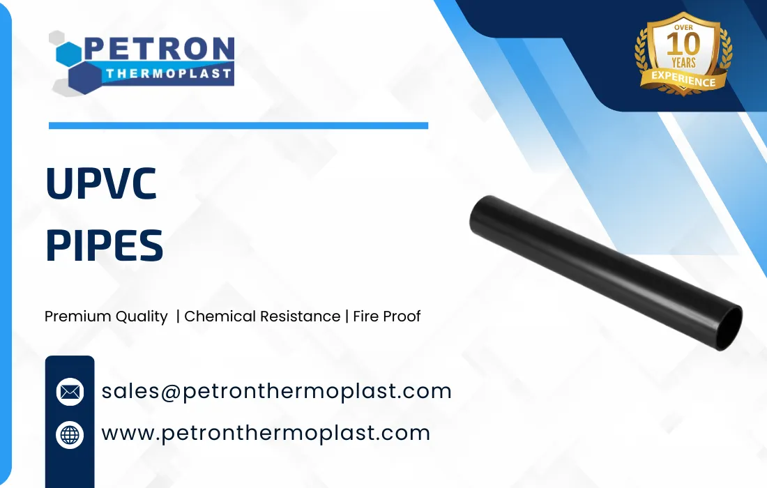
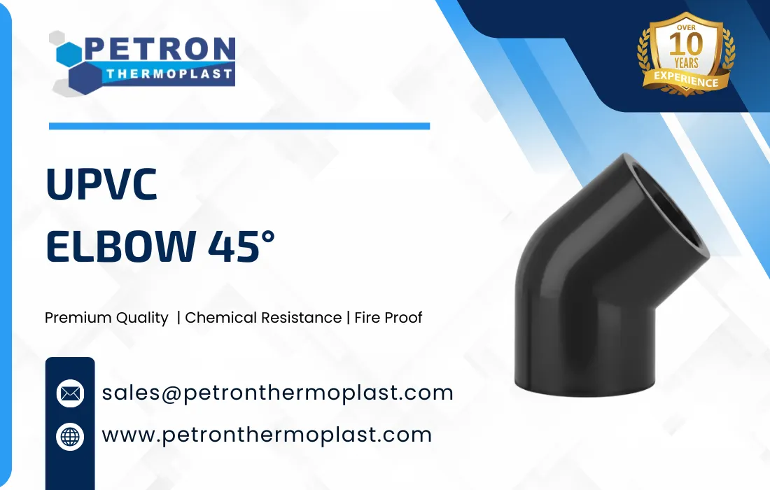
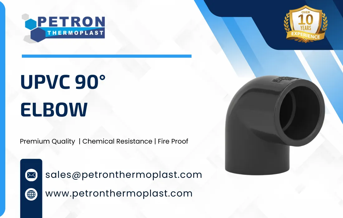
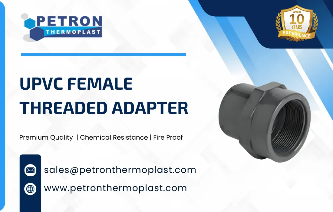
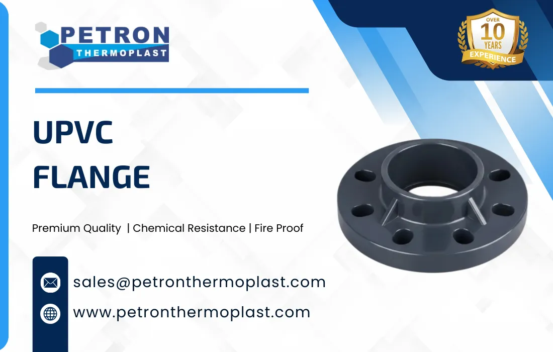
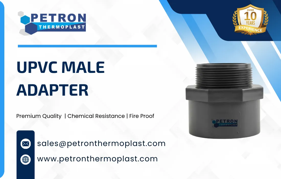
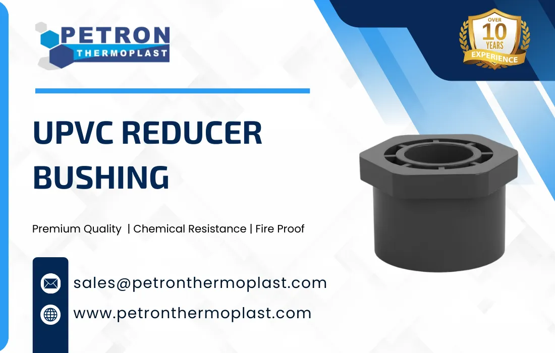
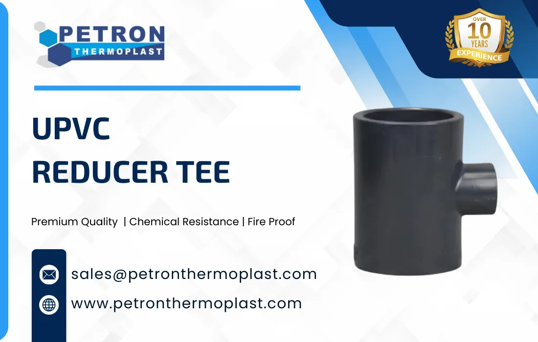
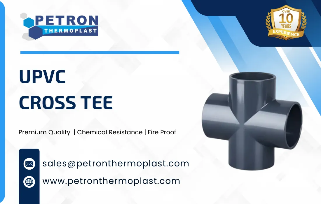
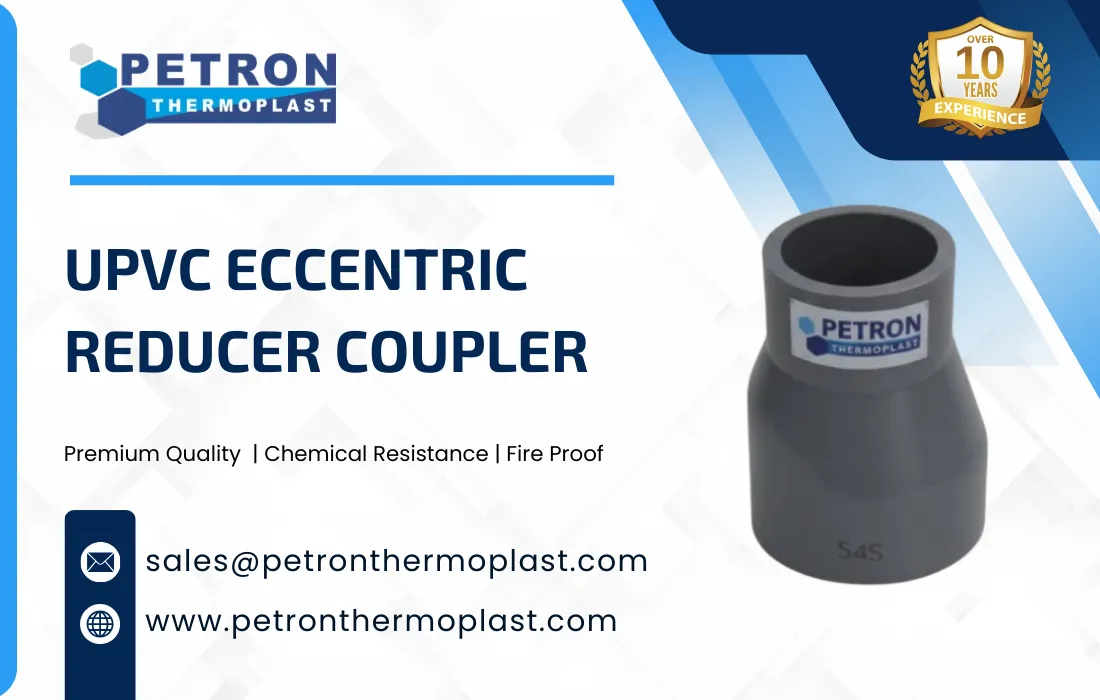
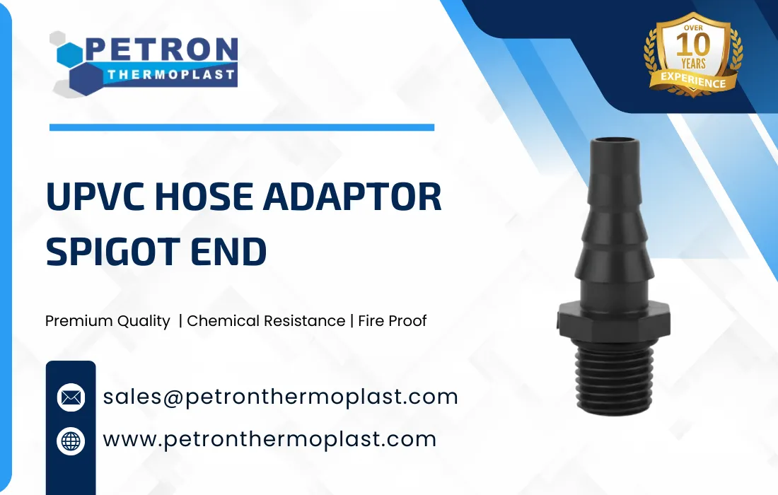
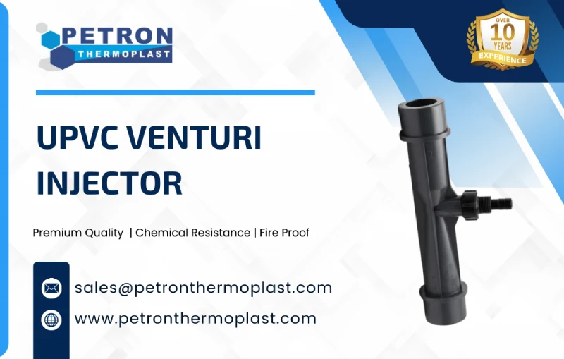
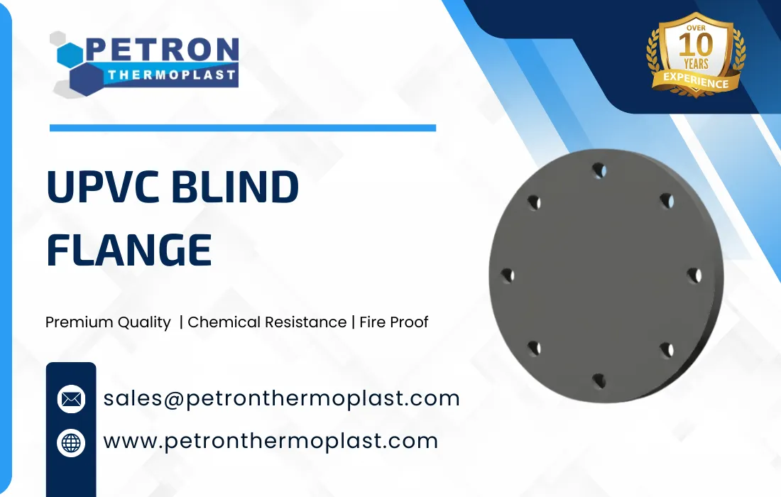
Corrosion Resistant – Immune to rust, scaling, and chemical corrosion; suitable for chemical, wastechemical, and many chemical lines.

Smooth Internal Bore – Low friction loss and minimal pressure drop, improving flow efficiency.

High Mechanical Strength
Rigid, impact-resistant construction with good tensile and compressive strength.

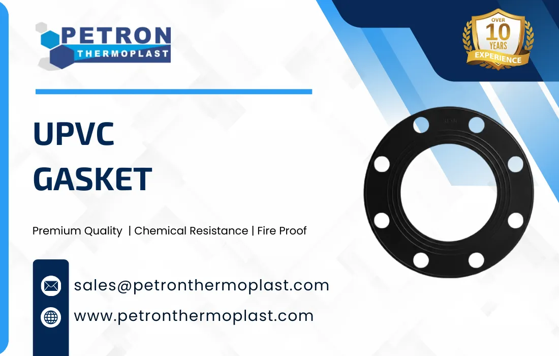
Excellent Chemical Resistance – Resistant to acids, alkalis, salts, and most industrial chemicals.

Lightweight Construction – Easier handling, transport, and installation compared to metal fittings.

Leak-Proof Solvent Cement Joint – Designed for solvent welding, ensuring strong, permanent, and leak-free connections.

Dimensional Accuracy – Precision molded for consistent wall thickness and proper socket depth.

Long Service Life – Non-aging material with high resistance to environmental degradation.

Low Maintenance – No painting, coating, or corrosion protection required.

Pressure Rated – Suitable for pressure applications as per relevant standards (e.g., PN6, PN10, PN16).

Temperature Resistance – Suitable for cold chemical and low-temperature fluid systems (typically up to 60°C).

Electrical Insulation – Non-conductive material, safe for electrical and underground applications.

Eco-Friendly & Non-Toxic – Lead-free and suitable for potable chemical systems.

Standard Compliance – Manufactured as per ASTM / ISO / DIN / BS / IS standards (depending on region).

ASTM uPVC Reducer Coupler – Schedule 40

Reducer Size (in)Max Working Pressure (psi)Max Working Pressure (bar)
1 × ½45031
1½ × 133023
2 × 133023
3 × 228019
4 × 228019
4 × 326018
6 × 422015
8 × 618012


ASTM uPVC Reducer Coupler – Schedule 80

Reducer Size (in)Max Working Pressure (psi)Max Working Pressure (bar)
1 × ½85058
1½ × 163043
2 × 163043
3 × 240028
4 × 240028
4 × 337026
6 × 432022

ISO / Metric uPVC Reducer Coupler (PN Rating)

PN ClassMax Working Pressure @ 20 °CTypical Applications
PN66 bar (87 psi)Drainage, low pressure
PN1010 bar (145 psi)Chemical supply
PN1616 bar (232 psi)Industrial / irrigation
PN2020 bar (290 psi)High-pressure systems

Temperature Derating Table (uPVC)

Temperature (°C)Pressure Factor
20–231.00
300.88
400.62
500.38
PropertyTypical ValueTest Method / Standard
MaterialUnplasticized Polyvinyl Chloride (uPVC)ASTM D1784
Density1.38 – 1.45 g/cm³ASTM D792
Specific Gravity1.38 – 1.45ASTM D792
ColorGrey / WhiteManufacturer Standard
Surface FinishSmooth, glossyVisual
Hardness (Shore D)80 – 85ASTM D2240
Tensile Strength≥ 45 MPaASTM D638
Flexural Strength≥ 80 MPaASTM D790
Modulus of Elasticity2.5 – 3.2 GPaASTM D638
Impact Strength (Izod, Notched)≥ 2.5 kJ/m²ASTM D256
Vicat Softening Temperature≥ 80°CASTM D1525
Coefficient of Thermal Expansion6.0 – 8.0 × 10⁻⁵ /°CASTM D696
Thermal Conductivity0.14 – 0.16 W/m·KISO 8302
Water Absorption (24 hrs)≤ 0.5%ASTM D570
Electrical ConductivityNon-conductiveIEC 60093
FlammabilitySelf-extinguishingUL 94 V-0 / V-1
Repairing Service

Custom Product Manufacturing Available

If you are searching for customized product designs that meet your requirements, don’t worry. Petron Thermoplast also offers custom product manufacturing services to meet the unique needs of various industries. Work with our expert engineers to create custom designs suited for your application.

Benefits of UPVC Reducer Coupler

Reducing from a main UPVC header to a smaller distribution line

Irrigation laterals where branch lines require smaller pipe diameters

Drainage and rainwater downpipe transitions between sizes

Utility chemical lines in residential, commercial, and light industrial projects

Quick repair work when replacing a damaged section with an available pipe size

Clean size transition without extra adapters or multiple joints

Improves alignment and reduces stress concentration at the diameter change

Supports faster installation and simpler site layout modifications

Helps reduce turbulence compared to abrupt, improvised transitions

Types & Connections of UPVC Reducer Coupler

Types of UPVC Reducer Couplers

  • Concentric UPVC  Reducer Coupler
    Connects two different pipe sizes with a common center line. Commonly used in vertical pipelines and general plumbing.

  • Eccentric UPVC Reducer Coupler
    Has offset center lines to keep the top or bottom level constant. Used in horizontal pipelines to avoid air pockets.

  • Socket × Socket UPVC Reducer Coupler
    Both ends have sockets to join two pipes of different diameters using solvent cement.

  • Socket × Spigot UPVC Reducer Coupler
    One end has a socket and the other a spigot, allowing connection flexibility where space is limited.

  • Threaded UPVC Reducer Coupler
    Used where threaded connections are required for easy installation or dismantling.

  • Pressure UPVC Reducer Coupler
    Designed to withstand high-pressure applications like water supply systems.

  • Drainage (Non-Pressure)UPVC  Reducer Coupler
    Used in low-pressure or gravity-flow drainage systems.

Connection Method (Step-by-Step)

  • Pipe Cutting
    Cut both pipes square to the axis
    Remove burrs and sharp edges
  • Dry Fit Check
    Insert pipes into reducer coupler without cement
    Ensure proper depth and alignment
  • Surface Cleaning
    Clean pipe ends and coupler sockets
    Use uPVC cleaner or dry cloth
  • Apply Solvent Cement
    Apply evenly on pipe outside and coupler socket inside
    Use recommended uPVC solvent cement
  • Joint Assembly
    Push pipe fully into socket
    Give a quarter-turn for even cement distribution
  • Holding Time
    Hold joint for 30–60 seconds
    Prevent movement during initial setting
  • Curing Time
    Allow curing as per cement manufacturer
    Typically 24 hours before pressure testing

Common uses of UPVC Reducer Coupler

Joining rebars of two different diameters (e.g., 25mm to 20mm)

Joining rebars of two different diameters (e.g., 25mm to 20mm)

Reducing bar diameter for structural design optimization

Enabling easier handling of upper rebars in vertical structures.

Enhancing seismic performance in transition zones

Providing strong, code-compliant mechanical splices

Why Choose Petron Thermoplast?

Custom combination available(32mm to 25mm, 25mm to 20mm, etc).

Tested for tensile, fatigue, and dynamic loads

Bulk production capabilities with on-time delivery

Corrosion-resistant coating for durability

Preferred supplier for top civil infrastructure companies