


Custom Product Manufacturing Available
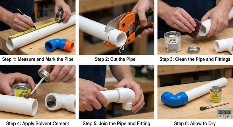
a) Preparation
- Inspect pipes and fittings for cracks, dirt, or damage.
- Clean the surfaces with a dry cloth; avoid solvents that can damage PVDF.
- Check pipe alignment to ensure proper fitting without stress.
b) Joining Methods
- Socket Fusion
- Heat both pipe and fitting surfaces with a socket fusion tool.
- Insert the pipe into the fitting and hold until the material cools and fuses.
- Creates a strong, leak-proof joint.
- Butt Fusion
- Heat the ends of the pipe and fitting using a butt fusion machine.
- Press them together under controlled pressure until fused.
- Ideal for large-diameter pipes.
- Electrofusion
- Use electrofusion fittings with embedded coils.
- Apply electric current to melt the fitting onto the pipe.
- Provides a reliable, sealed connection, especially in tight spaces.
c) Installation Tips
- Avoid mechanical stress: PVDF is strong but can crack under bending or impact.
- Support pipes adequately with clamps or hangers to prevent sagging.
- Maintain minimum bend radius to prevent deformation (usually 20× pipe diameter).
- Allow thermal expansion: PVDF has a higher expansion rate than metals.
2. Maintenance of PVDF Pipe Fittings
a) Routine Inspection
- Check for leaks, cracks, or discoloration.
- Inspect joints for stress or misalignment.
b) Cleaning
- Flush with clean water or compatible solvents.
- Avoid abrasive cleaning methods that could scratch the inner surface.
c) Pressure and Temperature Monitoring
- Ensure operation within rated pressure (PN10/PN16) and temperature limits.
- Use pressure relief valves where necessary to prevent overpressure damage.
d) Replacement & Repairs
- Replace damaged fittings promptly; PVDF fittings cannot always be repaired once cracked.
- Use proper joining methods when adding new sections.