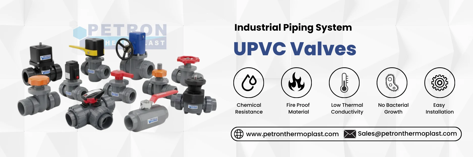
A UPVC valve is a valve that is used to control, start, stop, or regulate the flow of liquids in a piping system. Because UPVC is rigid and corrosion-resistant, these valves are widely used in oil & gas supply, irrigation, chemical processing, and industrial pipelines. A UPVC Valve is a flow control type valve that is used in piping systems where compressed air is used to automatically open or close the valve. A UPVC Valve is used to control the rotation of a disc, and inside the valve, for regulating or isolating the flow of liquids or gases.
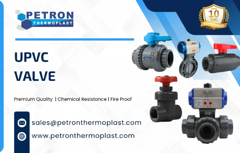
UPVC Valves, also known as PVC Valves, are frequently utilized for a variety of industrial and commercial purposes, including pipe linkages and other applications. Unplasticized Polyvinyl Chloride valves are naturally damage-resistant and are the closest ally. UPVC valves are made of high-quality Unplasticized Polyvinyl Chloride and are custom-designed to meet customers’ needs. When it comes to controlling the flow of heavy liquids and grains. UPVC valves are quite effective.
Inspect the valve for damage, cracks, or foreign particles.
Check that the pipe diameter matches the valve size.
2.Pipe Preparation
Cut the pipe squarely using a pipe cutter or fine saw.
Deburr the pipe edges to remove rough surfaces.
Clean the pipe end and valve socket with a clean, dry cloth.
3.Dry Fit Test
Insert the valve into the pipe without adhesive to check fit and alignment.
Ensure that flow direction matches valve marking (arrows on valve body).
4. Solvent Cement / Gluing (for Socketed Valves)
Apply UPVC primer (if required) on both pipe and valve socket.
Apply UPVC solvent cement evenly on the pipe and the valve socket.
Insert the pipe into the valve socket with slight twisting to ensure full coverage.
Hold for a few seconds to prevent movement.
5. Threaded Valves (if applicable)
Apply PTFE tape or thread sealant on male threads.
Screw the valve hand-tight, then use a wrench to tighten 1–2 turns (do not over-tighten).
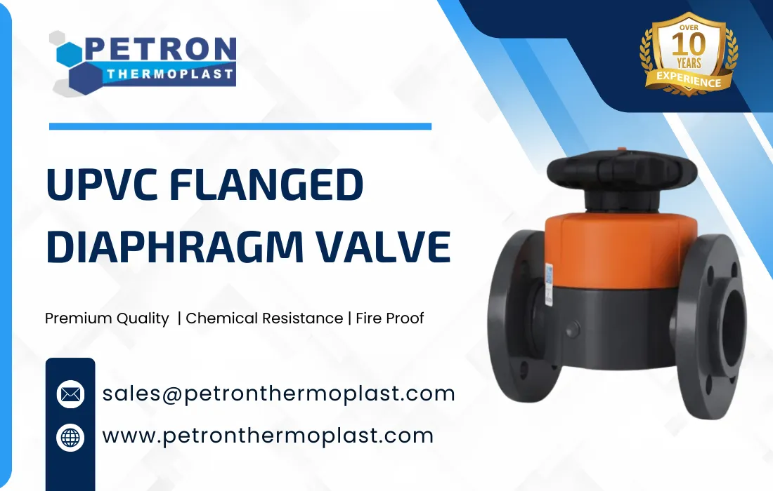
6. Flanged Valves (if applicable)
Use gaskets between valve flanges and pipe flanges.
Tighten flange bolts in a criss-cross pattern for uniform pressure.
7. Alignment and Orientation
Ensure the valve is properly aligned with the pipeline.
Check that the operating handle has sufficient space for movement.
8. Curing / Setting
Allow solvent cement joints to cure as per manufacturer instructions (usually 15–30 min initial, 24 hours full strength).
9. Testing
Conduct a pressure test according to system requirements:
Slowly fill the line with the chemical
Check for leakage at joints or the valve body
Operate the valve to ensure smooth opening and closing
10. Final Commissioning
Open and close the valve several times to ensure proper function.
Document the installation for maintenance and inspection.
Size and Dimensions – adjusting diameter, length, or port size to fit unique pipe systems.
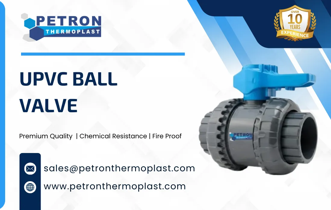
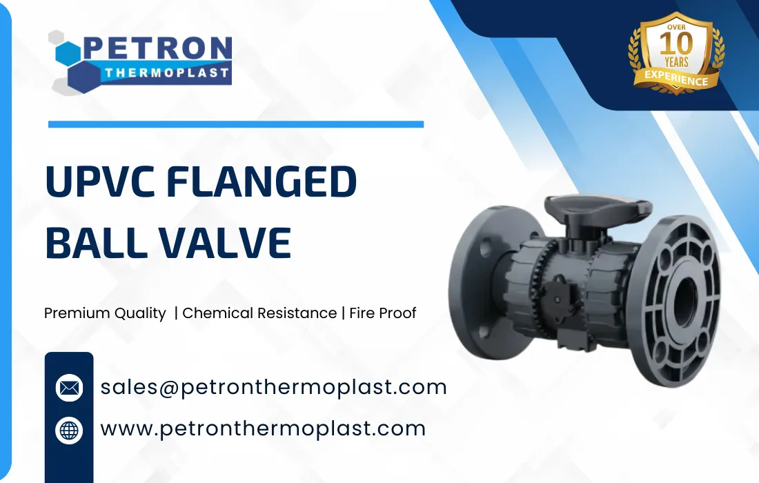
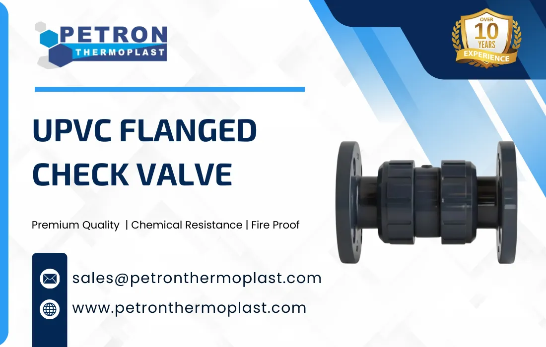
Valve Type – converting standard ball, gate, or check valves into designs suitable for particular flow control needs.
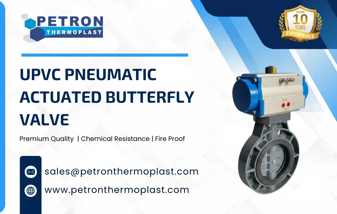
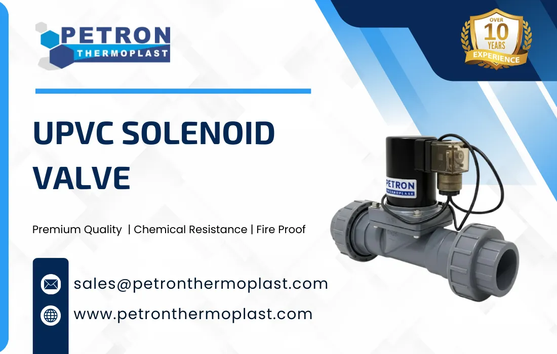
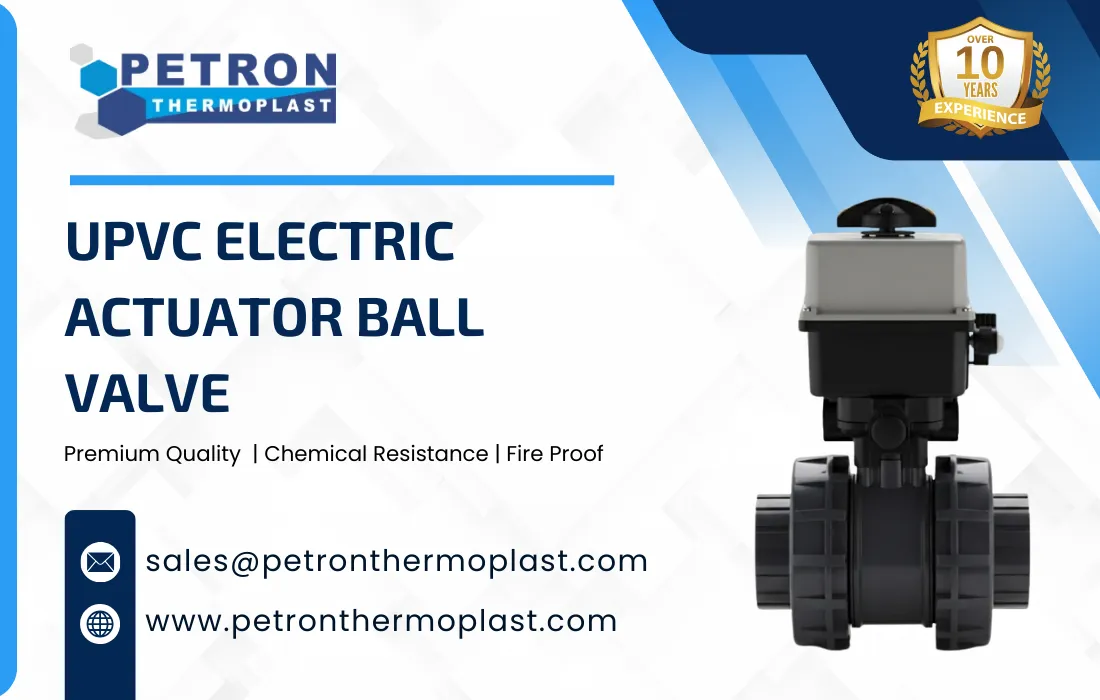
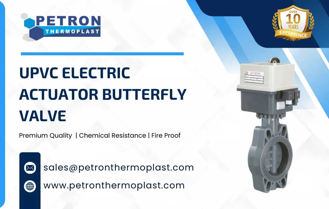
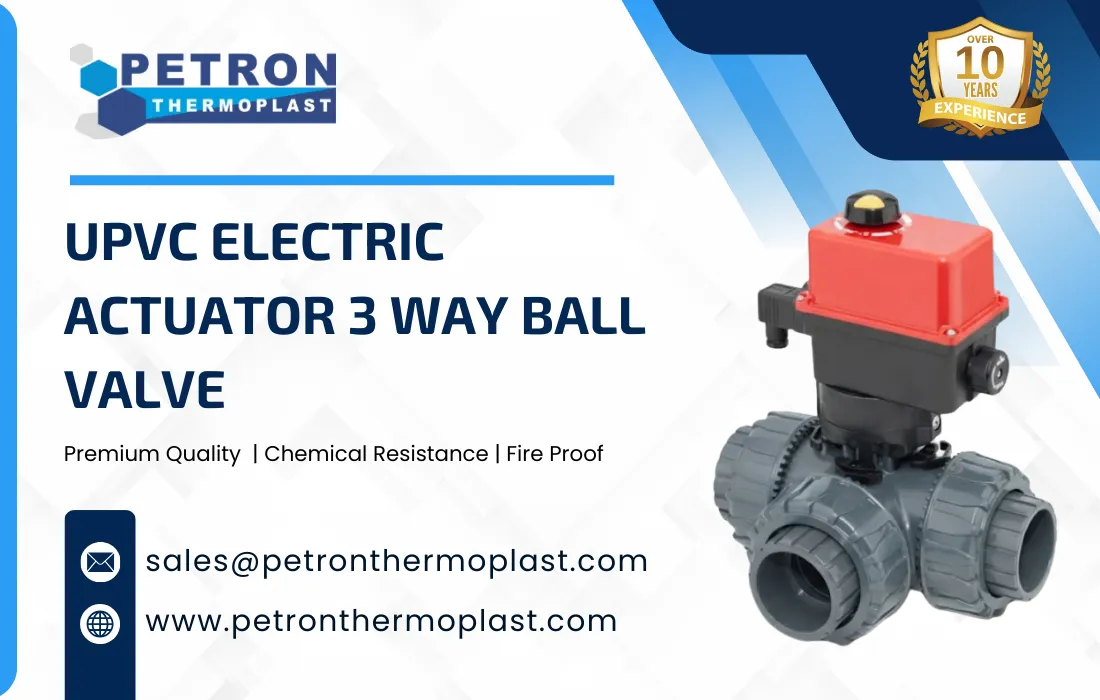
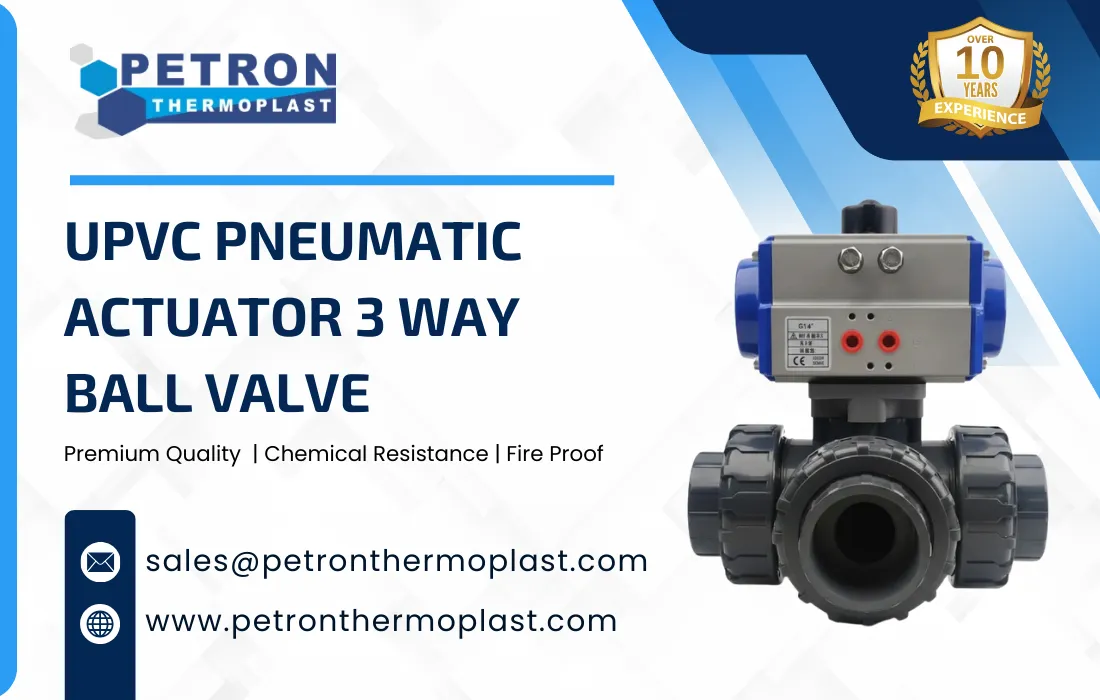
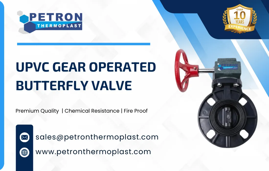
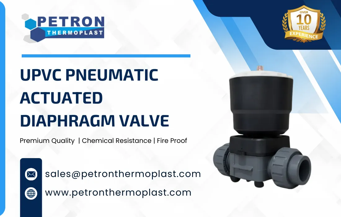
Actuation Mechanism – adding manual handles, gear operators, or motorized actuators for automated control.
Pressure and Temperature Ratings – selecting reinforced uPVC or adding design features to handle specific pressures or chemical environments.
Connection Type – customizing end connections (socket, threaded, flanged) to match existing piping systems.
Special Features – adding features like flow meters, isolation mechanisms, or anti-corrosion coatings.
1. Raw Material Preparation
UPVC Resin Selection: Choose rigid UPVC (unplasticized) with additives for UV resistance, impact strength, and chemical resistance.
Additives: Stabilizers, lubricants, and fillers are mixed with the resin to improve processability and durability.
2. Compounding
The UPVC resin and additives are blended into a homogeneous mixture using high-speed mixers.
This ensures consistent properties for molding.
3. Injection Molding / Extrusion
Injection Molding: Common for valves like ball or gate valves. The molten UPVC is injected into a pre-designed mold under high pressure to form the valve body.
Extrusion: Used for producing tubes or certain fittings that may be cut and machined into valve components.
4. Cooling and Demolding
After molding, the valve is cooled to solidify and then removed from the mold.
Proper cooling prevents warping or deformation.
5. Machining / Finishing
Drilling / Boring: For valve ports and stem holes.
Threading or Socket Formation: To create end connections compatible with pipes.
Polishing / Deburring: Removes rough edges for smooth operation and sealing.
6. Assembly
Install internal components like ball, disc, stem, and seals.
Lubricants or O-rings may be added to improve sealing and ease of operation.
If you are searching for customized product designs that meet your requirements, don’t worry. Petron Thermoplast also offers custom product manufacturing services to meet the unique needs of various industries. Work with our expert engineers to create custom designs suited for your application.
Petron Thermoplast understands specifying a UPVC valve means considering the entire lifecycle within your specific system, whether it’s for a hydrocarbon application boiler & steam application, a chemicals production process, or an effluent treatment plant. By choosing Petron Thermoplast, you gain a partner committed to ensuring the valve’s connection is as reliable as the valve itself. By systematically evaluating the system’s pressure, temperature, and maintenance, Petron Thermoplast is a trusted manufacturer and supplier of high-quality UPVC Valves, engineered to deliver reliable filtration, long service life, and consistent performance across demanding industrial applications. Our products are designed to meet the needs of EPC contractors, OEMs, and process industries worldwide.
Proven Manufacturing Expertise
With years of experience in thermoplastic engineering, Petron Thermoplast produces UPVC Valve that meets strict dimensional accuracy, pressure ratings, and quality benchmarks.
Superior UPVC Material Quality
Our UPVC Valves are manufactured using premium-grade, corrosion-resistant UPVC, ensuring excellent performance in chemical, industrial, and water fluid handling systems.
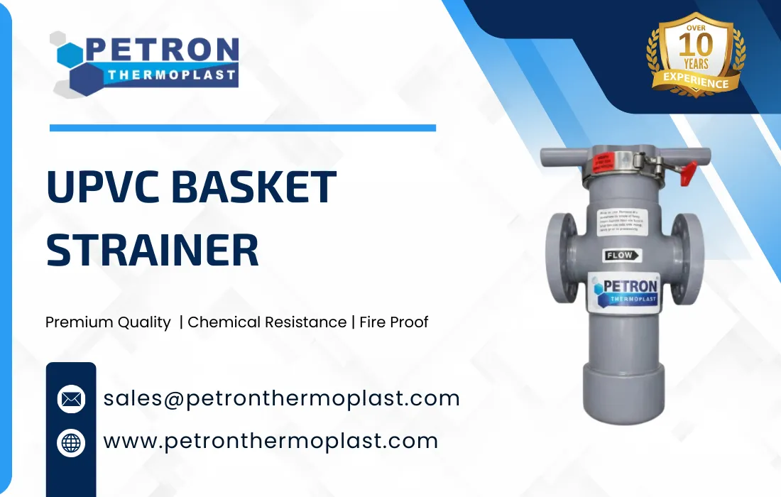
Precision-Engineered Strainer Elements
Each UPVC Valve is equipped with a high-strength, removable screen designed for efficient particle filtration while maintaining optimal flow rates.
UPVC stands out as a durable, cost-effective, and versatile material for industrial and agricultural applications. Its superior heat and chemical resistance make it a preferred choice across industries. With UPVC prices staying pretty reasonable, it’s a no-brainer for anyone looking to get good quality without spending a ton. UPVC valves play an integral role in the assembly and repair of UPVC piping systems. Their unique properties, including heat and corrosion resistance, combined with ease of use, make them an indispensable tool in industrial applications, and beyond. As industries continue to evolve, the importance of reliable materials like UPVC and its valve will only increase, highlighting the need for professionals to be well-equipped with this essential knowledge. By understanding the applications and advantages of UPVC valves, professionals can make informed decisions that ensure the longevity and effectiveness of their projects.
At Petron Thermoplast, we deliver top-grade UPVC valves that are engineered for industrial efficiency, safety, and longevity. With unbeatable chemical resistance, mechanical strength, and thermal stability, our UPVC valves are the perfect choice for demanding environments.
UPVC Valves are widely used due to their reliable sealing and ease of operation.
Can UPVC valves be used in high pressure systems?
They can be used in some pressure rated applications, but suitability depends on system requirements and valve design.
What is the purpose of a UPVC valve?
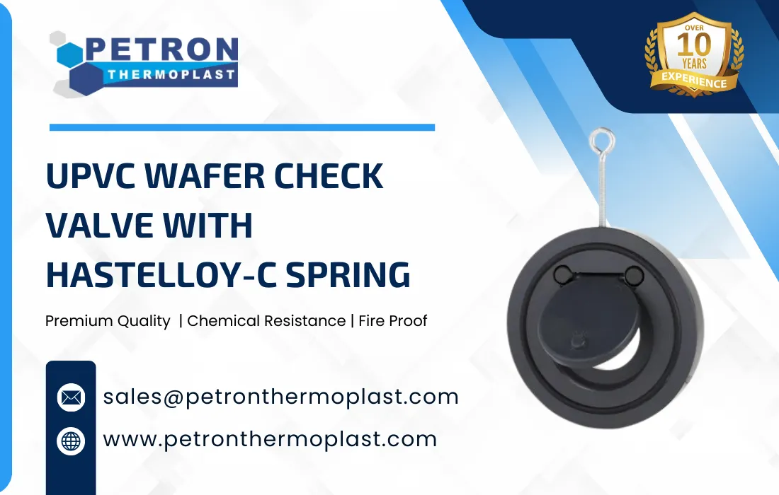
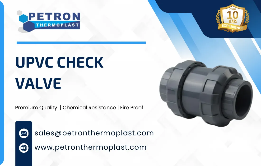
Valves prevent reverse flow, protecting equipment and maintaining system integrity.
Do UPVC valves require regular maintenance?
Should valve material match pipe material?
Should valve material match pipe material?
Valve materials should always be compatible with both the pipe material and the media being transported.
What temperature can UPVC Valve withstand?
UPVC valves can handle continuous operating temperatures up to 90–95°C and short-term exposure up to 110°C, making them suitable for high-temperature industrial applications.
Are UPVC valves chemically resistant?
Yes. UPVC Valves offer excellent resistance to acids, alkalis, salts, and many industrial chemicals, making them ideal for chemical processing, oil, gas treatment, and industrial piping systems.
Are UPVC Valve flame retardant?
Yes. UPVC is inherently flame retardant and self-extinguishing. It typically complies with UL 94 V-0 / V-1 flame resistance standards.
Can UPVC valve be machined easily?
Absolutely. UPVC valve have excellent machinability and can be easily turned, drilled, milled, or threaded using standard machining tools.