When compared to other popular polymers, ABS has superior mechanical characteristics such as impact resistance, toughness, and stiffness.
To increase impact resistance, toughness, and heat resistance, several changes can be performed.
Increase the quantities of polybutadiene in ratio to styrene and also acrylonitrile to increase impact resistance, but this alters other characteristics. At lower temperatures, impact resistance does not deteriorate as quickly.
With restricted loads, the stability under load is excellent. ABS Valve and Pipe Fittings are very easy installation and reliable for used.
ABS Valves are a pressure piping system that is both strong and rigid. ABS piping is a low-cost option for both commercial and residential applications.
It’s a great option for get-togethers. Acrylonitrile Butadiene Styrene (ABS) is an amorphous, impact-resistant, opaque thermoplastic commonly utilised in the plastics industry.
We are able to provide ABS Valve to our clients because of our extensive experience in this field The thermoplastic is composed out of three monomer units, as the name suggests:
Acrylonitrile: Ammonia and propylene are used to make acrylonitrile, a synthetic monomer.
Butadiene: Butadiene is a monomer that is generated as a by-product of steam crackers along with ethylene.
Styrene: Dehydrogenation of ethylbenzene produces styrene, a monomer.
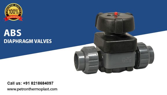
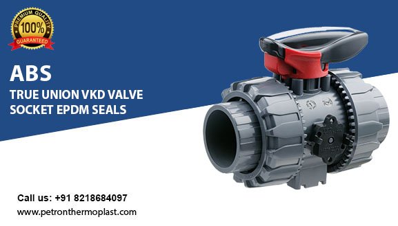
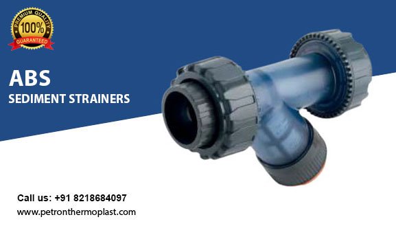
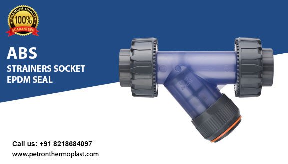
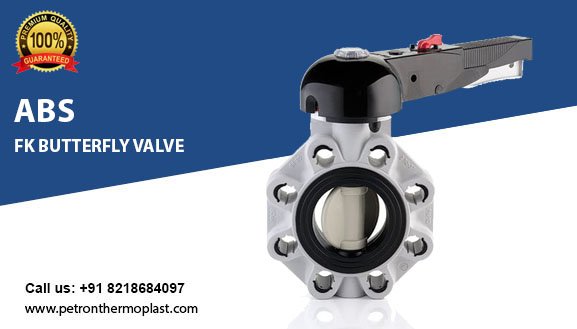
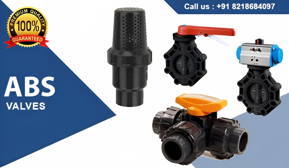
Advantages of ABS Valves
ABS valve and piping installation both commercial and residential applications. It won’t peel, flake, rot, disintegrate, fade, or leak (unless punctured).
It’s perfect for usage outside, underground, in extreme temperatures, and anywhere else where it won’t be exposed to direct sunlight.
Plumbers frequently choose it for drain, waste, and vent pipe systems. ABS pipe is also commonly used in sewage systems for drainage and as an electrical insulator.
Applications of ABS Valves
ABS thermoplastic is an excellent replacement for metals in many automobile parts that are looking to save weight. Dashboard components, seat backs, seat belt pieces, door loners, handles, instrument panels, pillar trim, and other elements are commonly utilised.
ABS is used in a variety of everyday household appliances and consumer items, including control panels, vacuum cleaner housings, food processor housings, refrigerator liners, and so on.
Computer keyboards, electronic enclosures, and other electrical and electronic applications
ABS plastic is used in construction applications such as ABS pipes and fittings. This is due to characteristics like strong impact strength and rust and corrosion resistance.
ABS Valves Technical Details
Density
Test method
ISO 1183 – ASTM D792
Unit of measurement
g/cm3
Value
1.38
Modulus of elasticity
Test method
ISO 527
Unit of measurement
MPa = N/mm2
Value
3200
IZOD notched impact strength at 23°C
Test method
ASTM D256
Unit of measurement
J/m
Value
50
Ultimate elongatio
Test method
ISO 527
Unit of measurement
%
Value
50
Shore hardness
Test method
ISO 868
Unit of measurement
Shore D
Value
80
Tensile strength
Test method
ISO 527
Unit of measurement
MPa = N/mm2
Value
50
VICAT softening point (B/50)
Test method
ISO 306
Unit of measurement
°C
Value
76
Heat distortion temperature HDT (0.46 N/mm2)
Test method
ASTM D648
Unit of measurement
°C
Value
86
Thermal conductivity at 23° C
Test method
DIN 52612-1 – ASTM C177
Unit of measurement
W/(m °C)
Value
0.16
Coefficient of linear thermal expansion
Test method
DIN 53752 – ASTM D696
Unit of measurement
m/(m °C)
Value
8 x 10⁻⁵
Limiting Oxygen Index
Test method
ISO 4859-1 – ASTM D2863
Unit of measurement
%
Value
45
ABS Valves Standard Details
Production of the PVC-U lines is carried out according to the highest quality standards and in full compliance with the environmental restrictions set by the applicable laws in force and in accordance with ISO 14001. All products are made in accordance with the quality guarantee system in compliance with ISO 9001.
Standard Details
ANSI B16.5
Pipe flanges and flanged fittings-NPS 1/2 to NPS 24 mm / inch
ASTM D 2464
Standard Specification for Threaded Poly Vinyl Chloride (PVC) Plastic Pipe Fittings
ASTM D 2467
Standard Specification for Poly Vinyl Chloride (PVC) Plastic Pipe Fittings, Schedule 80
BS 10
Specification for flanges and bolts for pipes, valves and fittings
BS 1560
Flanges for pipes, valves and fittings (Class designated). Steel, cast iron and copper alloy flanges. Specification for steel flanges
BS 4504
Flanges for pipes, valves and fittings (PN designated).
DIN 2501
Flanges, dimensions
DIN 2999
Whitworth thread for threaded pipes and fittings
DIN 3202
Overall valve dimensions
DIN 3441-2
Dimensions of PVC-U ball valves
DIN 8062
Dimensions of PVC-U pipes
DIN 8063
Dimensions of PVC-U fittings
DIN 16962
PVC-C fittings for butt-welding or socket fusion, dimensions
DIN 16963
Pipe connections and pipe components for pressurised fluids in HDPE
DVS 2204 – 2221
Solvent welding of thermoplastic materials PVC-U
EN 558-1
Industrial valves – face-to-face and centre-to-face dimensions of metal valves for use in flanged pipe systems – Part 1: PN designated valves
EN 1092-1
Flanges and their joints – Circular flanges for pipes, valves and accessories – Part 1: Steel flanges, PN designated
EN ISO 1452
Characteristics of fittings and pipes in PVC-U for piping systems intended
for water supply
SOLVENT WELDING INSTRUCTIONS<
Solvent welding, or cement jointing, is the longitudinal joining system for connecting rigid PVC-U pipes and fittings. The “cementing” is carried out using adhesives/cements obtained by dissolving PVC-U polymer in a solvent mixture. This solvent liquefies the walls of the pipe and/or fitting, allowing the constituent material to chemically combine and be subse-quently welded. Chemical welding allows permanent joints be achieved possessing
chemical and mechanical strength characteristics identical to those of the pipes and fittings joined. The adhesives/solvent cements must be selected according to the type of thermoplastic resin to weld, in that the nature of the solvents vary, as does the weld material contained in them. It must be remembered, therefore, that all the solvent cements designed for joining thermoplastic pipes and fittings must be used to join pipes, fittings and valves of the same material. Before starting any solvent welding operations, the efficiency and condition of the equipment used and the pieces to be assembled must be verified, in particular the uniformity, fluidity and expiry date of the solvent cement.
FIG.1
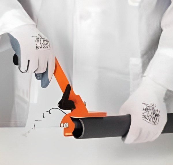
Cut the pipe perpendicular to its axis to obtain a clean square section, preferably using a wheeled pipe cutter designed specifically for thermoplastic pipes.
FIG.2
Chamfer the outer edges of the pipe in order to ensure that it enters the socket of the fitting at an angle of 15°. The chamfering operation must be carried out at all costs, otherwise the lack of chamfer can lead to the solvent being scraped off the surface of the fitting, thus compromising the effectiveness of the joint. The chamfering must be carried out using the appropriate chamfering tool.
FIG.3
Measure the depth of the socket of the fitting to the internal shoulder and mark the corresponding distance on the end of the pipe. For more de- tails, refer to the “Socket depth, cement and chamfer length” table.
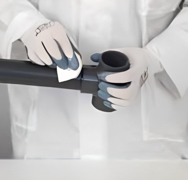
FIG.4
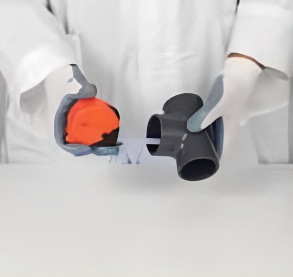
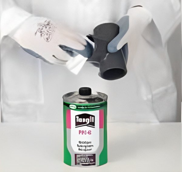
Using an clean paper towel or applicator soaked in Cleaner-Primer, remove any traces of dirt or grease from the outer surface of the pipe for the entire cement-ing length. Repeat the same operation on the internal surface of the socket of the fitting: leaving the surfaces softened. Leave the surfaces to dry for a few minutes before applying the solvent cement. Remember that, in addition to cleaning the joint surfaces, the Cleaner-Primer also performs the important role of softening and preparing the surface to receive the solvent, an operation that enables a perfect joint to be obtained.
FIG.5
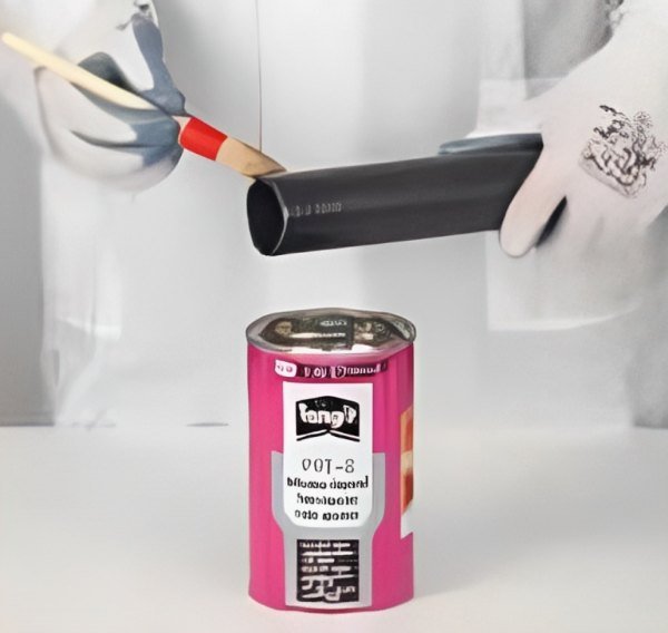
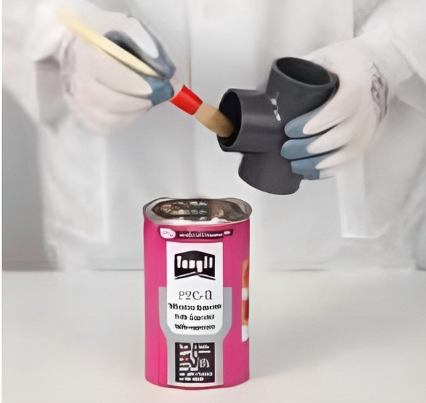
Apply the solvent cement in a uniform manner longitudinally over both parts to be assembled (outer surface of the pipe and internal coupling surface of the fit-ting) using an applicator or suitably sized coarse brush.
For more detailed information, refer to the “Brush-applicator characteristics and dimensions” table. It is advisable to use an applicator/brush of dimension not less than half the di-ameter of the pipe. The solvent cement must be applied along the entire length
of the joining surface of both the pipe and the fitting: – for the entire joint length of the pipe previously marked on the outer surface (fig. 1) – for the entire depth of the socket as far as the internal shoulder (fig.2)
FIG.6
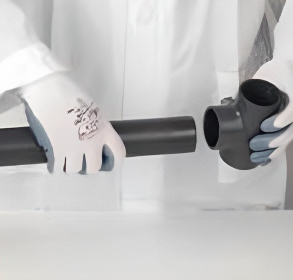
Fully insert the pipe into the fitting immediately and without any rotation. Only after this operation will it be possible to slightly rotate both ends (max. 1/4 of a turn between pipe and fitting). This rotation movement will render the layer of applied solvent cement more uniform.
Note: The pipe must be inserted in the fitting as soon and as quick as possible (after no more than 20-25 seconds is recommended). Depending on the external diameter of the pipe and, as a result, possible handling difficulties, the insertion of the pipe into the fitting must be carried out: – manually by one person for external diameters < 90 mm. – manually by two people for external diameters from d 90 to d < 160 mm. – using mechanical pipe-pullers for external diameters > 160 mm.
FIG.7
The pipe must be inserted in the fitting as soon and as quick as possible (after no more than 20-25 seconds is recommended). Depending on the external diameter of the pipe and, as a result, possible handling difficulties, the insertion of the pipe into the fitting must be carried out: – manually by one person for external diameters < 90 mm. – manually by two people for external diameters from d 90 to d < 160 mm. – using mechanical pipe-pullers for external diameters > 160 mm.
FIG.8
Immediately after fully inserting the pipe in the fitting, apply pressure to the joined parts for a few seconds. Then use crepe paper or a clean cloth to remove any excess solvent cement from the outer surfaces, and from internal surfaces where possible (fig. 9).
FIG.9
Solvent cement drying: the joined parts must be left to stand in order to allow the solvent cement to set naturally without generating any unnecessary stress. The setting time depends on the amount of stress that the joint will be placed under. In particular, the following minimum setting times must be respected according to the ambient temperature: • before handling the joint: – from 5 to 10 minutes for ambient T. > 10°C – from 15 to 20 minutes for ambient T. < 10°C • for repair joints on pipes of any size or pressure not subject to hydraulic testing: – 1 hour for each atm of applied pressure • for joints in pipes and fittings of any diameter subject to pressure testing up to PN 16: – minimum 24 hours The solvent cement setting times indicated are valid at ambient temperature (approx. 25°C.). For particular climatic conditions (humidity, temperature, etc…), we recommend you contact our technical services department and/or the solvent cement manufacturer for more information (fig. 10 and 11).