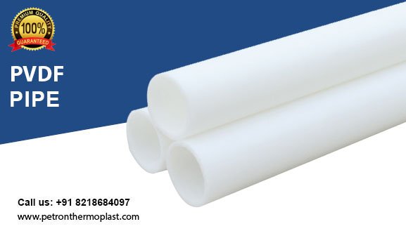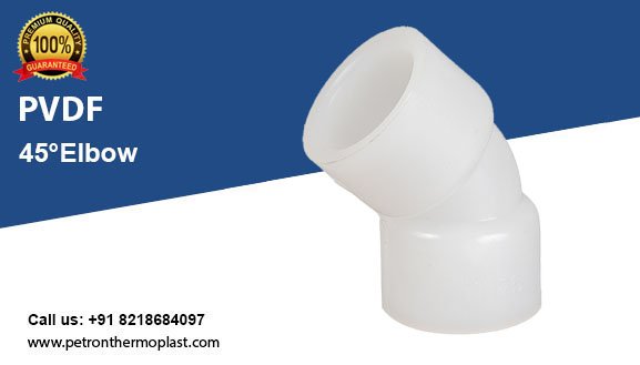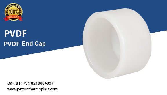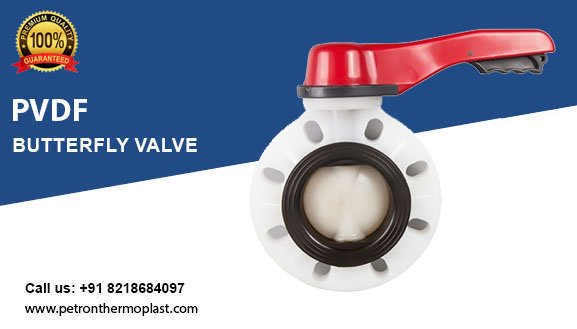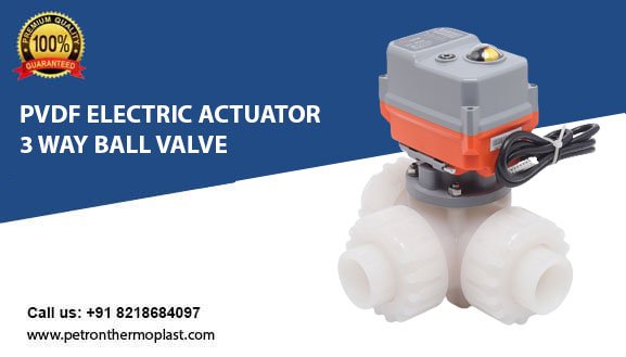
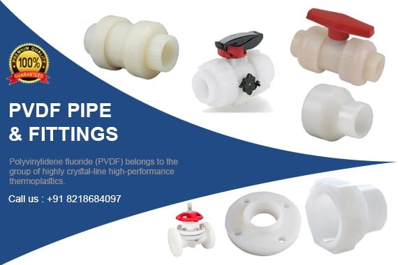
PVDF Pipe and Fittings
PVDF Pipe and Fittings are excellent for handling a wide range of chemical solvents and materials since they are resistant to reacting with most of these substances. Among the most often used commercial and industrial PVDF pipes are polyvinylidene fluoride pipes and fittings.
Our various PVDF piping meets all domestic and international quality specifications and criteria. Our entire collection can be delivered in the allowed period. This pipe is melt-blown so that you can extrude it.
To strengthen the connection between different materials, you can chemically etch the conduit. It is handy for metal pipes if you apply a PVDF coating. PVDF Piping system is in stock to satisfy the demands of our valued customers in all possible ways.
Polyvinylidene fluoride (PVDF) belongs to the group of highly crystal-line high-performance thermoplastics. PVDF retains its high level of stiffness even within the upper temperature range.
The material is highly resistant to the majority of organic and inorganic media, as well as being physiologically safe and offering the benefits of low flammability.
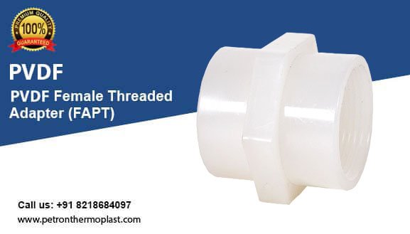
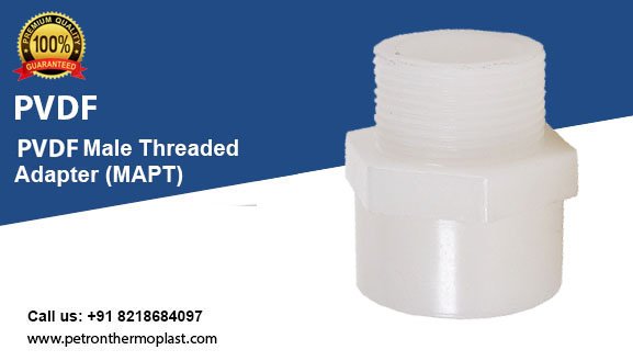
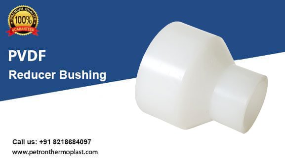
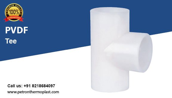
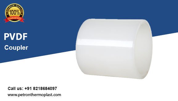
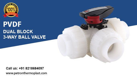
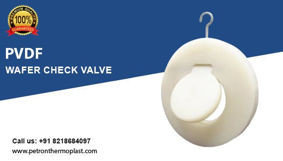
PVDF Pipe Fittings Range
In what way is PVDF made
PVDF is manufactured through a polymerization procedure called chemical synthesis. Plastic-like polyethylene, PVC, and polypropylene polymers are made through polymerization. There is a wide range of quality and consistency in plastic pipe and fittings, including polyvinylidene fluoride (PVDF) pipe and fittings. In other words: ‘monomer.’ While PVC piping can be rated up to 248°F (120°C), PVDF piping has a temperature limit of 248°F (120°C). PVDF uses radioactive processing waste, synthesizing compounds (corrosive sulphuric acid), and using air plenums.
It suggests that the single vinylidene fluoride (VDF) units are connected from start to end to describe a lengthy molecular structure known as a polymer, which is, in this case, a plastic, and polyvinylidene fluoride (PVDF), also known as Kynar. In the manufacture of PVDF, the base starting material is VDF. Typically, non-piezoelectric alpha compounds are handled. To attain the piezoelectric beta stage, the material needs to be expanded or strengthened. PVDF Pipe membrane is exempt. Due to lingering tensions in the process, the beta stage structure’s thin films are far-fetched enough to be believable.
Features of PVDF Pipe and Fittings
- Excellent Chemical Resistance – Resistant to acids, solvents, and harsh chemicals, making it ideal for industrial applications.
- High-Temperature Tolerance – Can withstand temperatures up to 150°C (302°F) without losing structural integrity.
- Superior Mechanical Strength – High tensile strength and impact resistance ensure long-lasting durability.
- UV & Weather Resistance – Performs well in outdoor and exposed environments without degradation.
- Low Permeability – Prevents contamination and ensures safe fluid transportation in critical applications.
- Smooth Interior Surface – Reduces friction, minimizes pressure loss, and prevents scaling or buildup.
- Lightweight & Easy Installation – Simplifies handling, transportation, and installation compared to metal alternatives.
- Corrosion-Free Performance – Unlike metal pipes, PVDF does not rust, corrode, or degrade over time.
- High Purity & FDA Compliance – Suitable for ultrapure applications, including pharmaceuticals and food processing.
- Long Service Life – High wear resistance ensures extended operational life with minimal maintenance.
Properties
PVDF
• Excellent chemical resistance
• Physiologically safe (in accordance with BfR and FDA)
• Broad temperature range
• Low flammability (in accord-ance with DIN 4102 B1 and FM 4910)
• Good hydraulic properties due to smooth pipe interior
• Exceptional ageing resistance
Applications of PVDF Pipe and Fittings
- Chemical Processing Industry – Used for transporting corrosive chemicals, acids, and solvents due to its excellent chemical resistance.
- Water Treatment Plants – Ideal for handling aggressive fluids in desalination, wastewater treatment, and ultra-pure water applications.
- Semiconductor & Electronics – Used in ultrapure water systems, chemical delivery lines, and cleanroom environments.
- Pharmaceutical & Biotechnology – Ensures contamination-free fluid handling in sterile and high-purity applications.
- Food & Beverage Industry – Suitable for transporting food-grade fluids, meeting FDA and hygienic standards.
- Oil & Gas Industry – Used in pipelines for chemical injection, offshore drilling, and refining processes.
- Power Plants – Ideal for cooling systems, chemical dosing, and fluid transport in nuclear and thermal power plants.
- Pulp & Paper Industry – Handles corrosive chemicals used in bleaching and paper processing applications.
- Metal Finishing & Electroplating – Used in acid lines, plating baths, and wastewater treatment due to its corrosion resistance.
- Laboratories & Research Facilities – Preferred for handling aggressive chemicals in high-purity lab environments.
PVDF Pipe and Fittings:
• Substantial thermal conductivity, even while operating at elevated temperatures
• Well over 100 years service life, even in highly acidic situations
• Very pure materials using natural methods.
• Welded joints should be made more secure with better welding technology.
PVDF Uses
1. Resistance profile, mechanical and thermal strength, Magno-electric properties, and fluid covering structures are all PVDF Pipe & Fittings Manufacturer’s features that have seen significant improvements with upgrades. PVDF pipe and fittings demonstrate high mechanical strength, piezoelectric and pyroelectric capabilities, and outstanding processability.
2. PVDF Fittings In semiconductors, pipes, and fittings are generally manufactured, welded, or injected. A cross-linked sealed cell foam can be used for several purposes, such as flight and aircraft. Additionally, it can be applied to various food items since the FDA, and completely safe approve it.
3. This PVDF powder is a valuable paint component that is utilized in metallic paints. They are high-gloss, superior PVDF paint. The PVDF paints are employed in several residential construction projects? Off-white, brick-and-masonry towers, as well as skyscrapers and metal rooftops, are present.
4. This also applies to carbon-filtered supercapacitors and other electrochemical applications utilizing a folio section.
5. Filters made from PVDF pipe suppliers are used in filtering equipment and the covers for CCTV cable, alarm system cable, and other cable types.
Get Quick Information
PVDF Pipe & Fittings Technical Details
| MaterialColor Density Surface tension Linear expansion coefficient E-modulus Thermal conductivity Surface resistivity | Polyvinylidene Fluoride (PVDF) opaque ~1.78g/cm (ISO 1183 / ASTM D 92) 30–35mJ/m 0.12–0.18 m/mK (DIN 53752) ≥1700 N/mm (EN ISO 527 / ASTM D 790) 0.19W/mK (DIN 52612) 5×10 cm (IEC 60093) |
| Dimension | d20 (1⁄2”)–d315 (12”) in accordance to ISO 10931 |
| Pressure rating | Pipes/fittings: 20–110 mm PN 16 (232 PSI); 160–315 mm PN 10 (150 PSI) Valves: separate specification |
| Temperature rating | from −20 C to 140 C (−4 F to 284 F) |
| Production | Fittings/valves: injection molded Pipes: extruded and stress relieved (ISO 10931-2) Valves: injection molded (additional available oil free treated and paint compatible / ilicon free) |
| Surface finish | Inner surface Ra ≤ m (20 in) for injection molded and extruded components |
| Marking | All components are embossed with a permanent identification during the production process to ensure full traceability. Lot No Material Dimension Pressure Rating |
| Testing and inspection (ISO 10931) | Inclusions Visual inspection Surface finish Dimension tolerance Pressure testing |
| Approvals/conformance | DIBt ASME BPE FDA CFR 21 177.2510 USP 25 class VI (physiological non-toxic) FM-4910 listing) UL 723 ASTM E-84 25/50 for building plenums for sizes 20–75 mm |
| Welding technology | BCF® Plus, bead and crevice free fusion, size d20 (1⁄2”) – d110 (4”) IR Plus®, infrared fusion (DVS 2207-6), size d20 (1⁄2”) – d315 (12”) Butt fusion (DVS 2207-15), size d20 (1⁄2”) – d315 (12”) Socket fusion (DVS 2207-15), size d20 (1⁄2”) – d63 (2”) |
| Documentation* | Certificate of Conformance with FDA, USP EN 10204 2.2 EN 10204 3.1 |
| Packing** | Multiple components single bagged in specified bag |
| Labeling | Brand Name Product Description Code Number Material Dimension |
| Main applications | Uses include delivery of pharmaceutical grade purified water (PW) and DI water, using hot water, steam chemical or ozone sanitization. Due to its excellent chemical resistance it is widely used in chemical distribution systems. |
Application Limits of Pipes and Fittings Made of Thermoplastic Materials
(25 years operation with safety factor incorporated )


Pipe, PN 16, PVDF-Standard 25/50
Model:
• Material: PVDF
• Supplied in 5m (16.4 foot) length
• Certified for building air plenum according to UL 723 ASTM E-84 25/50, sizes 20-75mm
| d(mm) | FM | Part No. | lbs/meter | e(mm) | di(mm) |
|---|---|---|---|---|---|
| 20 | BCF, IR | * 175 484 203 | 0.463 | 1.9 | 16.2 |
| 25 | BCF, IR | * 175 484 204 | 0.593 | 1.9 | 21.2 |
| 32 | BCF, IR | * 175 484 205 | 0.959 | 2.4 | 27.2 |
| 40 | BCF, IR | * 175 484 206 | 1.241 | 2.4 | 35.2 |
| 50 | BCF, IR | * 175 484 207 | 1.874 | 3.0 | 44.0 |
| 63 | BCF, IR | * 175 484 208 | 2.403 | 3.0 | 57.0 |
| 75 | BCF, IR | * 175 484 209 | 3.417 | 3.6 | 67.8 |

Pipe, PN 16, PVDF-Standard
Model: • Material: PVDF • Supplied in 5m (16.4 foot) length • Material: PVDF * on request
| d(mm) | FM | Part No. | lbs/meter | e (mm) | di (mm) | |
|---|---|---|---|---|---|---|
| 90 | BCF, IR | * 175 480 210 | 4.916 | 4.3 | 81.4 | |
| 110 | BCF, IR | * 175 480 211 | 7.341 | 5.3 | 99.4 | |
| * | 250 | IR | * 175 481 218 | 11.9 | 226.2 | |
| * | 280 | IR | 175 481 219 | 13.4 | 253.2 | |
| * | 315 | IR | * 175 481 220 | 15.0 | 285.0 |

Pipe, PN 10, PVDF-Standard
Model:
• Material: PVDF
• Supplied in 5m (16.4 foot) length
| d(mm) | PN(bar) | FM | Part No. | lbs/meter | e(mm) | di(mm) |
|---|---|---|---|---|---|---|
| 160 | 10 | IR | * 175 480 668 | 10.009 | 4.9 | 150.2 |
| 200 | 10 | IR | * 175 480 669 | 15.851 | 6.2 | 187.6 |
| 225 | 10 | IR | * 175 480 670 | 19.731 | 6.9 | 211.2 |
| 250 | 10 | IR | * 175 480 671 | 24.471 | 7.7 | 234.6 |
| 315 | 10 | IR | * 175 480 674 | 38.801 | 9.7 | 295.6 |
- Material
- PVDF
- Colour
- Natural
- Dimensions
- Standard length: 5 m
- Note
- Other lengths on request
- Standards
- ISO 10931
| Pressure Pipe | SDR 41 | SDR 33 | SDR 21 | SDR 17.6 | SDR 17 | SDR 11 | SDR 7.4 |
|---|---|---|---|---|---|---|---|
| 16 | 1.9 | ||||||
| 20 | 1.9 | ||||||
| 25 | 1.9 | ||||||
| 32 | 2.4 | ||||||
| 40 | 2.4 | ||||||
| 50 | 3.0 | ||||||
| 63 | 2.0 | 3.0 | |||||
| 75 | 2.3 | 3.6 | |||||
| 90 | 2.8 | 4.3 | |||||
| 110 | 3.4 | 5.3 | |||||
| 125 | 3.9 | 6.0 | |||||
| 140 | 4.3 | 6.7 | |||||
| 160 | 4.9 | 7.7 | |||||
| 180 | 5.5 | ||||||
| 200 | 6.2 | ||||||
| 225 | 6.9 | ||||||
| 250 | 7.7 | ||||||
| 280 | 8.6 | ||||||
| 315 | 9.7 |
PRESSURE PIPE
Pressure pipes for PRESSURE PIPE connection system by butt or socket welding.
| Technical specifications | |
|---|---|
| Size range | d 16 ÷ d 110 (mm) |
| Nominal pressure | SDR 21 (PN16) with water at 20° C /SDR 33 (PN10) with water at 20° C |
| Temperature range | -40 °C ÷ 140 °C |
| Coupling standards | Welding: EN ISO 10931. Can be coupled to pipes according to EN ISO 10931 |
| Reference standards | Construction criteria: EN ISO 10931 Test methods and requirements: EN ISO 10931 Installation criteria: DVS 2201-1, DVS 2207-15, DVS 2208-1 |
| Material | PVDF |
- Material
- PVDF
- Colour
- Natural
- Dimensions
- Standard length: 5 m
- Non-standard lengths on request
- Note
- with or without pre-treated
surface for direct lamination - Standards
- ISO 10931
| Liner pipe, pre-treated | Liner pipe, untreated | ||||||
| d mm | e mm | emm | |||||
|---|---|---|---|---|---|---|---|
| 32 | 2.4 | ||||||
| 40 | 2.4 | ||||||
| 50 | 3.0 | ||||||
| 63 | 3.0 | ||||||
| 75 | 3.0 | 3.0 | |||||
| 90 | 3.0 | 3.0 | |||||
| 110 | 3.0 | 3.0 | |||||
| 125 | 3.0 | 3.0 | |||||
| 140 | 3.0 | 3.0 | |||||
| 160 | 3.0 | 3.0 | |||||
| 180 | 3.0 | 3.0 | |||||
| 200 | 3.0 | 3.0 | |||||
| 225 | 3.0 | 3.0 | |||||
| 250 | 3.0 | 3.0 | |||||
| 280 | 3.5 | 3.5 | |||||
| 315 | 4.0 | 4.0 | |||||
| 355 | 5.0 | 5.0 | |||||
| 400 | 5.0 | 5.0 | |||||
REGRESSION CURVES
FOR PIPES IN PVDF
Regression coefficients according to
ISO 10931 for MRS

PRESSURE
VARIATION
ACCORDING TO
TEMPERATURE
For water and non-hazardous fluids
for which the material is classified
as CHEMICALLY RESISTANT (life ex-
pectancy 25 years). In other cases,
a reduction of the nominal pressure
PN is required.

Installation instructions
It is important to know the right process of installation of PVDF. The processes differ for threaded and flanged joints.
For threaded joints:
To guarantee the hydraulic seal of the joint on fittings and valves with a threaded female end, we recommend you perform the following operations:
- Start winding some PTFE sealing tape on the outside of the threaded male end, taking care not to obstruct the through-hole on the pipe, fitting, or valve;
- Complete the first winding layer by winding the tape clockwise until you reach the root of the thread. Remember to keep the tape taut throughout the entire process;
- Press on the tips of the thread to make sure the tape adheres fully to the support clip;
- Increase the thickness of the PTFE layer by continuing to apply the taut tape and winding it clockwise until you achieve the optimal level;
- Connect the previously sealed male end to the female end and proceed manually by screwing the two elements;
- Make sure the layer of PTFE is not removed during screwing, as this would compromise the hydraulic seal of the joint;
- Complete screwing the two ends exploiting the entire length of the thread with the aid of a strap wrench or similar tool;
- Avoid tightening the elements too much, as this could damage the threads or cause stress to the elements themselves.
For flanged joints:
- Insert the possible backing ring onto the pipe, before proceeding with the installation of the stub;
- In the event of a fixed flange, check the drilling is correctly aligned with the counter flange;
- Check that the position of the counter flange takes into account the overall dimensions of the face to face distance of the components;
- Insert the flat gasket between the stubs (this step is not necessary for butterfly valves), making sure the sealing surfaces of the flanges to be welded have not been separated by an excessive distance, since this would cause it to compress;
- Proceed with solvent welding or welding of the fixed flanges or stub (in the case of backing rings) following the welding or solvent welding instructions provided by FIP;
- Insert all the bolts, washers, and nuts;
- Once the cooling time is up, proceed with tightening the bolts in a “cross-wise” order;
- Complete the bolt tightening process using a torque wrench until the tightening torque values shown in the table are reached.
Why Choose PVDF Pipe Fittings from Petron Thermoplast?
1. Exceptional Chemical Resistance
PVDF (Polyvinylidene Fluoride) pipe fittings offer outstanding resistance to acids, bases, solvents, and other aggressive chemicals, making them ideal for industrial and chemical processing applications.
2. High-Temperature Tolerance
PVDF fittings can withstand temperatures up to 150°C (302°F) without losing mechanical strength, making them suitable for high-temperature fluid handling.
3. Superior Mechanical Strength
With high tensile strength and impact resistance, PVDF fittings maintain their durability even under extreme conditions, ensuring a long service life.
4. UV and Weather Resistance
Unlike many plastics, PVDF resists UV radiation and harsh weather conditions, making it perfect for both indoor and outdoor applications.
5. Low Permeability & High Purity
PVDF has low moisture absorption and excellent barrier properties, ensuring contamination-free transport of sensitive fluids in industries like pharmaceuticals, semiconductors, and food processing.
6. Corrosion-Free & Long-Lasting
Unlike metal fittings that corrode over time, PVDF pipe fittings remain unaffected by rust, ensuring long-term performance with minimal maintenance.
7. Smooth Interior Surface
PVDF fittings have a low-friction surface, reducing pressure loss and preventing scale buildup, which enhances fluid flow efficiency.
8. FDA & NSF Compliance
PVDF fittings are safe for food, beverage, and pharmaceutical applications, complying with FDA, NSF, and other industry standards.
9. Lightweight & Easy to Install
Compared to metal fittings, PVDF pipe fittings are lightweight, easy to handle, and simple to install, reducing labor and installation costs.
10. Wide Range of Applications
From chemical processing and water treatment to oil & gas, power plants, and metal finishing, PVDF fittings are widely used across multiple industries.
GET THE LATEST PVDF Pipe Fittings Manufacturers PRICES ON YOUR EMAIL
Final Conclusion
PVDF pipes and fittings from Petron Thermoplast are the ultimate solution for industries requiring high-purity, corrosion-resistant, and durable piping systems. With exceptional chemical resistance, high-temperature tolerance, UV stability, and mechanical strength, PVDF pipes are the preferred choice for chemical processing, semiconductor manufacturing, pharmaceuticals, water treatment, and other demanding applications. At Petron Thermoplast, we are committed to providing premium-quality PVDF piping solutions that ensure long-term reliability, efficiency, and safety. Our products meet industry standards and certifications, making them ideal for various critical industrial applications.
For customized PVDF piping solutions, expert guidance, and competitive pricing, contact Petron Thermoplast today and experience superior performance with advanced thermoplastic solutions!
FAQs
PVDF (Polyvinylidene Fluoride) pipe is a high-performance thermoplastic piping solution known for its excellent chemical resistance, high-temperature tolerance, and mechanical strength. It is widely used in chemical processing, water treatment, pharmaceuticals, and semiconductor industries.
PVDF pipes offer several advantages, including:
- Superior chemical resistance to acids, bases, and solvents
- High-temperature resistance up to 150°C (302°F)
- UV and weather resistance for outdoor applications
- Smooth interior surface for improved flow efficiency
- Long service life with minimal maintenance
Compared to PVC or CPVC, PVDF pipes offer:
- Higher temperature resistance
- Better chemical and UV resistance
- Greater mechanical strength and durability
While PVC and CPVC are more cost-effective, PVDF is preferred for high-purity and demanding applications.
Yes, PVDF pipes can be joined using methods like butt fusion, socket welding, and mechanical fittings, ensuring strong and leak-proof connections.
Yes, PVDF pipes comply with FDA, NSF, and other industry standards, making them safe for food, beverage, and pharmaceutical applications that require high purity and contamination-free transport.
You can purchase premium-quality PVDF pipes and fittings from Petron Thermoplast, a leading supplier of industrial thermoplastic piping solutions. Contact us today for the best deals and expert assistance!
